


START-UP
Unit Preparation —
Make sure that unit has been in-
stalled in accordance with these installation instructions and
applicable codes. Make sure that Start-Up Checklist has been
completed and filled out.
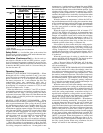
Return-Air Filters — Make sure correct filters are in-
stalled in filter tracks (see Table 1). Do not operate unit with-
out return-air filters.
Outdoor-Air Inlet Screens — Outdoor-air inlet screens
must be in place before operating unit.
Compressor Mounting — Compressors are inter-
nally spring mounted. Do not loosen or remove compressor
holddown bolts. On 48TJ014 units, remove the tiedown bands
that hold the compressors together.
Internal Wiring — Check all electrical connections in
unit control boxes. Tighten as required.
Refrigerant Service Ports — Each refrigerant sys-
tem has 4 Schrader-type service gage ports: one on the suc-
tion line, one on the liquid line, and two on the compressor
discharge line. Be sure that caps on the ports are tight. One
Schrader-type valve is located under both the high-pressure
switch and the low-pressure switch when ordered as an option.
Compressor Rotation — On 3-phase units with scroll
compressors, it is important to be certain compressor is
rotating in the proper direction. To determine whether or not
compressor is rotating in the proper direction:
1. Connect service gages to suction and discharge pressure
fittings.
2. Energize the compressor.
3. The suction pressure should drop and the discharge pres-
sure should rise, as is normal on any start-up.
If the suction pressure does not drop and the discharge
pressure does not rise to normal levels:
1. Note that the evaporator fan is probably also rotating in
the wrong direction.
2. Turn off power to the unit.
3. Reverse any two of the unit power leads.
4. Reapply power to the compressor.
The suction and discharge pressure levels should now move
to their normal start-up levels.
NOTE: When the compressor is rotating in the wrong
direction, the unit will make an elevated level of noise and
will not provide cooling.
Cooling — To start unit, turn on main power supply. Set
system selector switch at COOL position and fan switch at
AUTO. position. Adjust thermostat to a setting below room
temperature. Compressor starts on closure of contactor.
Check unit charge. Refer to Service, Refrigerant Charge
section, page 26.
Reset thermostat at a position above room temperature.
Compressor will shut off. Evaporator fan will shut off after
30-second delay.
TO SHUT OFF UNIT — Set system selector switch at OFF
position. Resetting thermostat at a position above room tem-
perature shuts unit off temporarily until space temperature
exceeds thermostat setting.
Main Burners — Main burners are factory set and should
require no adjustment.
TO CHECK ignition of main burners and heating controls,
move thermostat set point above room temperature and verify
that the burners light and evaporator fan is energized. After
ensuring that the unit continues to heat the building, lower
the thermostat setting below the room temperature and verify
that the burners and evaporator fan turn off (fan will turn off
only if fan selector switch is in the AUTO. position). Refer
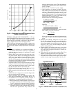
to Table 15 for the correct orifice to use at high altitudes.
NOTE: Upon a call for heat, the main burners will remain
on for a minimum of 60 seconds.
Heating
1. Purge gas supply line of air by opening union ahead of
gas valve. When gas odor is detected, tighten union and
wait 5 minutes before proceeding.
2. Turn on electrical supply and open manual gas valve.
3. Set system switch selector at HEATposition and fan switch
at AUTO. or ON position. Set heating temperature lever
above room temperature.
4. The induced-draft motor will start.
5. After a call for heating, the main burners should light within
5 seconds. If the burners do not light, then there is a
22-second delay before another 5-second try. If the burn-
ers still do not light, the time delay is repeated. If the
burners do not light within 15 minutes, there is a lockout.
To reset the control, break the 24 v power to W1.
6. The evaporator-fan motor will turn on 45 seconds after
the burners are ignited.
7. The evaporator-fan motor will turn off 45 seconds after
the thermostat temperature is satisfied.
8. Adjust airflow to obtain a temperature rise within the range
specified on the unit nameplate and in Table 1.
NOTE: The default value for the evaporator-fan motor
ON and OFF delay is 45 seconds. The Integrated Gas Unit
Controller (IGC) modifies this value when abnormal limit
switch cycles occur. Based upon unit operating condi-
tions, the ON delay can be reduced to 0 seconds and the
OFF delay can be extended to 180 seconds.
When one flash of the LED (light-emitting diode) is ob-
served, the evaporator-fan ON/OFF delay has been modi-
fied. If the limit switch trips at the start of the heating
cycle during the evaporator ON delay, the time period of
the ON delay for the next cycle will be 5 seconds less
than the time at which the switch tripped. (Example: If
the limit switch trips at 30 seconds, the evaporator-fan
ON delay for the next cycle will occur at 25 seconds.) To
prevent short-cycling, a 5-second reduction will only oc-
cur if a minimum of 10 minutes has elapsed since the last
call for heating.
The evaporator-fan OFF delay can also be modified. Once
the call for heating has ended, there is a 10-minute period
during which the modification can occur. If the limit switch
trips during this period, the evaporator-fan OFF delay will
increase by 15 seconds. A maximum of 9 trips can occur,
extending the evaporator-fan OFF delay to 180 seconds.
To restore the original default value, reset the power to
the unit.
TO SHUT OFF UNIT — Set system selector switch at OFF
position. Resetting heating selector lever below room tem-
perature will shut unit off temporarily until space tempera-
ture falls below thermostat setting.
23