


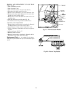

REMOVAL AND REPLACEMENT OF GAS TRAIN
(Fig. 45 and 46)
1. Shut off manual gas valve.
2. Shut off power to unit.
3. Slide out burner section side panel (not shown).
4. Disconnect gas piping at unit gas valve.
5. Remove wires connected to gas valve. Mark each wire.
6. Remove wires from ignitor and sensor wires at the Inte-
grated Gas Unit Controller (IGC).
7. Remove the 2 screws that attach the burner rack to the
vestibule plate.
8. Slide the burner tray out of the unit (Fig. 46).
9. To reinstall, reverse the procedure outlined above.
CLEANING AND ADJUSTMENT
1. Remove burner rack from unit as described in Removal
and Replacement of Gas Train section, above.
2. Inspect burners; if dirty, remove burners from rack.
3. Using a soft brush, clean burners and cross-over port as
required.
4. Adjust spark gap. See Fig. 47.
5. Reinstall burners on rack.
6. Reinstall burner rack as described in Removal and Re-
placement of Gas Train section, this page.
Replacement Parts — A complete list of replace-
ment parts may be obtained from any Carrier distributor upon
request.
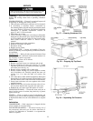
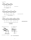
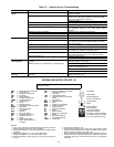
BURNER
SECTION
ROLLOUT
SWITCH
INDUCED-DRAFT
MOTOR
FLUE
EXHAUST
FLUE
EXHAUST
VESTIBULE
PLATE
MANIFOLD
PRESSURE TAP
GAS VALVE
Fig. 45 — Burner Section Details
Fig. 46 — Burner Tray Details
29