


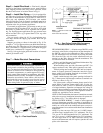

OPTIONAL PARABLADE ECONOMIZER — The op-
tional PARABLADE economizer hood assembly is pack-
aged and shipped in the filter section. Damper blades and
control boards are installed at the factory and the econo-
mizer is shipped in the vertical discharge position.
NOTE: Horizontal discharge block-off plate is shipped with
the air hood package. The PARABLADE economizer can
only be used for vertical discharge applications. Discard this
plate.
Assembly
1. Determine if ventilation air is required in building. If
so, determine the minimum amount to be supplied by
each unit and record quantity of ventilation air needed
for use in Step 7.
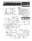
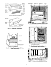
2. Remove filter access panel by raising panel and swing-
ing panel outward. Panel is now disengaged from track
and can be removed. No tools are required to remove
filter access panel. Remove outdoor-air opening panel.
See Fig. 18. Save panels and screws. Remove optional
economizer so the outdoor-air damper hood package can
be removed from the filter section.
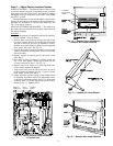
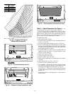
3. Assemble outdoor-air hood top and side plates as shown
in Fig. 19. Install seal strips on hood top and sides. Put
aside screen retainer and retainer screw for later assem-
bly. Do not attach hood to unit at this time.
4. On 012 and 014 units, install vertical discharge block-
off plate over duct openings. See Fig. 20.
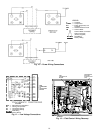
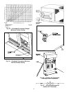
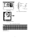
5. Slide economizer into unit and secure with screws. See
Fig. 29.
NOTE: Be sure to engage rear economizer flange under
tabs in vertical return-air opening.
6. Insert economizer plug into economizer harness. Re-
move tape from barometric relief damper. See Fig. 29.
7. If ventilation air is not required, proceed to Step 8. If
ventilation air is required, perform the following:
a. Make sure the factory-installed jumper is inplace across
terminals P and P1 on the economizer logic module.
T and T1 should be disconnected during adjustment.
b. The 2 potentiometers with slots for adjustment are
located on the face of the economizer logic module.
Turn the lower potentiometer fully clockwise. The
dampers should be fully closed. Turn the potentiom-
eter gradually counterclockwise until the desired po-
sition is reached.
c. Connect T and T1 to the 24 v power supply.
d. After installation is complete, calculate the mini-
mum airflow across the economizer. To calculate the
minimum airflow, the following data is needed: total
cfm (cfm
3
), temperature of the total cfm (T
3
), tem-
perature of the return air (T
1
), and temperature of the
entering outside air (T
2
). Cfm
1
is the return air cfm,
which will be the minimum airflow.
Insert the data into the following equations:
T
1
(cfm
1
)+T
2
(cfm
2
)
=T
3
cfm
3
cfm
2
= (cfm
3
– cfm
1
)
Therefore:
T
1
(cfm
1
)+T
2
(cfm
3
– cfm
1
)
=T
3
cfm
3
Use this equation to determine cfm
1
, which is the mini-
mum airflow across the economizer.
(T
3
–T
2
) cfm
3
cfm
1
=
(T
1
–T
2
)
If cfm
1
does not match the desired minimum airflow
from Step 1, re-adjust the minimum position setting
screw.
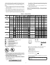
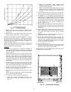
8. Determine the enthalpy changeover set point from
Fig. 30. The enthalpy changeover set point should be
set to return the outdoor air damper to the minimum po-
sition when enthalpy rises above the set point. The set-
tings are A, B, C, and D. Set the enthalpy changeover
per the setting in Fig. 30.
9. Replace outdoor-air opening panel using screws from
Step 2. Replace filter access panel. Ensure the filter ac-
cess panel slides along the tracks and is securely en-
gaged. See Fig. 31.
10. Fasten hood top and side plate assembly (Fig. 32) to
outdoor-air opening panel with screws provided.
11. Slide outdoor-air inlet screens into screen track on hood
side plate. While holding screens in place, fasten screen-
retainer to hood using screws provided. See Fig. 33.
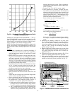
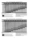
Fig. 28 — Durablade Economizer Barometric Relief
Damper Characteristics
ECONOMIZER CONTROL
MODULE/DAMPER ACTUATOR
WIRING
HARNESS
ENTHALPY
SENSOR
BAROMETRIC
RELIEF DAMPER
Fig. 29 — PARABLADE Economizer Installed in Unit
15