


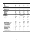
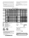

UNIT
48TJ
STANDARD
UNIT
WEIGHT
CORNER
WEIGHT
(A)
CORNER
WEIGHT
(B)
CORNER
WEIGHT
(C)
CORNER
WEIGHT
(D)
‘‘H’’ ‘‘J’’ ‘‘K’’ ‘‘L’’
Lb Kg Lb Kg Lb Kg Lb Kg Lb Kg ft-in. mm ft-in. mm ft-in. mm ft-in. mm
D/E/F008 870 395 189 86 161 73 239 109 280 127 1-2
7
⁄
8
378 3-5
5
⁄
16
1050 2-9
11
⁄
16
856 2- 2
7
⁄
16
672
D/E/F009 880 399 191 87 163 74 242 110 284 129 3-3
7
⁄
8
1013 3-5
5
⁄
16
1050 2-9
11
⁄
16
856 2- 2
7
⁄
16
672
D/E/F012 1035 469 225 102 192 87 285 129 333 151 2-5
7
⁄
8
759 4-1
5
⁄
16
1253 3-0
3
⁄
8
924 2-10
7
⁄
16
875
D/E014 1050 476 228 103 195 88 289 131 338 153 1-2
7
⁄
8
378 4-1
5
⁄
16
1253 3-0
3
⁄
8
924 2-10
7
⁄
16
875
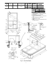
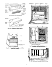
NOTES:
1. Dimensions in [ ] are in millimeters.
2. Center of gravity.
3. Direction of airflow.
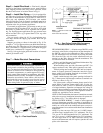
4. Onverticaldischarge units,ductworkto beattachedto accessoryroofcurbonly.For
horizontaldischargeunitsfield-suppliedflanges shouldbeattached tohorizontaldis-
charge openings, and all ductwork should be attached to the flanges.
5. Minimum clearance (local codes or jurisdiction may prevail):
a. Between unit (flue side) and combustible surfaces, 48 inches.
b. Bottom of unit to combustible surfaces (when not using curb) 1 inch.
Bottom of base rail to combustible surfaces (when not using curb) 0 inches.
c. Condenser coil,for proper airflow, 36 in.one side, 12 in.the other. Theside get-
ting the greater clearance is optional.
d. Overhead, 60 in. to assure proper condenser fan operation.
e. Between units, control box side, 42 in. per NEC (National Electrical Code).
f. Between unit and ungrounded surfaces, control box side, 36 in. per NEC.
g. Between unit and block or concrete walls and other grounded surfaces, control
box side, 42 in. per NEC.
h. Horizontal supply and return end, 0 inches.
6. With the exception of the clearance forthe condenser coil and combustion side as
stated inNotes 5a, b,and c,a removablefence or barricaderequires noclearance.
7. Units may be installed on combustible floors made from wood or Class A, B, or C
roof covering material if set on base rail.
8. The verticalcenter ofgravity is 1Ј-7Љ [483] upfrom thebottom of thebase rail. Hori-
zontal center of gravity is shown.
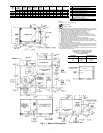
CONNECTION SIZES
A 1
3
⁄
8
Љ Dia [35] Field Power Supply Hole
B 2-
1
⁄
2
Љ Dia [64] Power Supply Knock-Out
C 1
3
⁄
4
Љ Dia [44] Charging Port Hole
D
7
⁄
8
Љ Dia [22] Field Control Wiring Hole
E
3
⁄
4
Љ—14 NPT Condensate Drain
F
1
⁄
2
Љ—14 NPT Gas Connection 48TJD008 & 009
3
⁄
4
Љ—14 NPT Gas Connection 48TJE/F008 & 009;
48TJD/E012,014, 48TJF012
G 2Љ Dia [51] Power Supply Knock-Out
Fig. 7 — Base Unit Dimensions
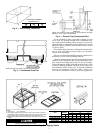
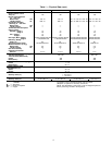
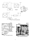
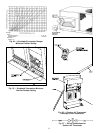
BOTTOM POWER CHART, THESE HOLES
REQUIRED FOR USE WITHACCESSORY
PACKAGES — CRBTMPWR001A00,
OR CRBTMPWR002A00
THREADED
CONDUIT SIZE
WIRE SIZE
REQUIRED HOLE
SIZES (MAX)
1
⁄
2
؆ 24 V
7
⁄
8
Љ [22.2]
3
⁄
4
؆ Power* 1
1
⁄
8
Љ [28.4]
1
1
⁄
4
؆ Power* 1
3
⁄
4
Љ [44.4]
*Select either
3
⁄
4
Љ or 1
1
⁄
4
Љ for power, depending on wire size.
7