


Installation
26 RTU Open
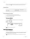
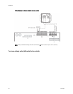
The sensor has a range of 0–2000 ppm and a linear 4-20 mA output. The CO2 sensor’s power requirements
exceed what is available at
J4 - 1 and 4. Provide a dedicated 24 Vac transformer or DC power supply.
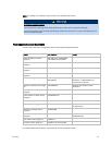
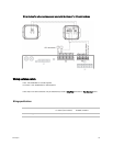
Wiring specifications
Cable from sensor to controller: If <100 ft (30.5 meters) 22 AWG, unshielded
If >100 ft (30.5 meters) 22 AWG, shielded
Maximum length: 500 feet (152 meters)
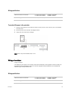
To wire the OAQ sensor to the controller
1 Wire the sensor to the controller. See appropriate diagram below.
2 Install a field-supplied dedicated 24 Vac transformer or DC power supply.
3 Apply power and verify sensor readings.
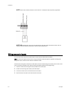
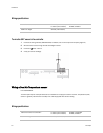
Wiring diagram for #33ZCSENCO2:
NOTE Sensor may be terminated at Input 1 or 2.
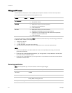
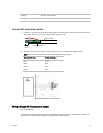
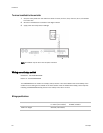
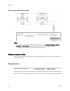
Wiring a Relative Humidity sensor
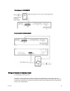
Wall sensor - Part #33ZCSENSRH-01
Duct sensor - Part #OPNSENRH-01
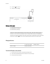
The Relative Humidity (RH) sensor may be used for zone humidity control (dehumidification) when applied to
a Carrier rooftop unit equipped with the Humidi-MiZer™ option. On units not equipped for dehumidification,
the sensor monitors humidity, but provides no control.
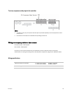
NOTE You cannot use a relative humidity sensor when using both a CO2 and OAQ sensor on the controller.