


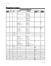

RTU Open 13
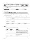
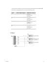
Channel
Number
Type
Signal
Function
Part Number
Wire/Terminal
Numbers
BO - 8
Alternate
Terminals
BO N/A - Relay Power Exhaust
N/A
J11
N/A
- 1 & 3
Legend
AI
- Analog Input
AO
- Analog Output
BI
- Digital Input
BO
- Digital Output
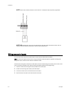
*
Safety Chain Feedback
- 24 Vac required at this wire to provide
Run Enabled
status. Provide a jumper from
J1
- 1 to
J1
- 9 if no
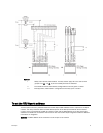
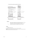
safeties are utilized. See To wire inputs and outputs 14 (page ) for additional information on the RTU Open wiring harness assembly
terminations.
** Default input function
*** Parallel screw terminal at
J5
(
J5
- 1 =
J2
- 6,
J5
- 3 =
J1
- 10,
J5
- 5 =
J1
- 2) may be used in place of the associated flying leads at
the harness (OPN-RTUHRN). See To wire inputs and outputs 14 (page ) for additional information.
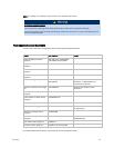
Input wiring specifications
Input
Maximum length
Minimum gauge
Thermistor
Shielding
1000 feet
(305 meters)
22 AWG Unshielded
4-20 mA 3000 feet
(914 meters)
22 AWG Unshielded
Binary input
1000 feet
(305 meters)
22 AWG Unshielded
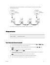
SPT (RNET) 500 feet
(152 meters)
22 AWG
4 conductor
Unshielded
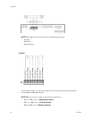
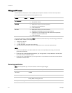
Inputs
These RTU Open inputs accept the following signal types:
These
inputs...
Support this
signal type...
1, 2
Description
4-20 mA The input resistance on the positive (+) terminal is 250 Ohms.
The Aux Power Out terminal is capable of supplying 24 Vdc to
a 4-20 mA transducer, but the total current demanded must
not exceed 40 mA. If the voltage measured from the Aux
Power Out terminal to Gnd is less than 18 Vdc, you need to
use an external power supply.
3, 5, 8, 9 Binary (24 Vac) 24 Vac voltage, resulting in a 25 mA maximum sense current
when the contacts are closed
6, 7, 10 Thermistor 10 kOhm at 77° F
11 100k Potentiometer Typically used for 33CZT56SPT Setpoint Offset Potentiometer