


4
I . Installation Instructions
1. INSPECT SHIPMENT carefully for any signs of
damage. All equipment is carefully manufactured,
inspected and packed. Our responsibility ceases upon
delivery of Boiler to the carrier in good condition. Any
claims for damage or shortage in shipment must be led
immediately against the carrier by the consignee. No
claims for variances or shortages will be allowed by
Boiler Manufacturer unless presented within sixty (60)
days after receipt of equipment.
2. BOILER INSTALLATION must conform to the
requirements of the authority having jurisdiction, or in
the absence of such requirements, to:
U.S.A. - National Fuel Gas Code, ANSI Z223.1.
When required by the authority having juris-
diction, the installation must conform to
ANSI/ASME No. CSD-1.
CANADA - "Installation Codes for Natural and LP Gas
Burning Appliances and Equipment, CAN/
CSA-B149.1.
3. These Gas Boilers are DESIGN CERTIFIED FOR
INSTALLATION ON COMBUSTIBLE FLOORING.
DO NOT INSTALL THESE BOILERS ON
CARPETING.
NOTICE
Do not drop boiler. Do not bump boiler jacket
against oor.
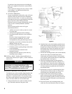
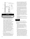
4. LOCATE BOILER in front of or behind installation
position before removing Crate. Locate on a level oor
as close to chimney as possible. For basement
installations, provide a solid base such as concrete, if
oor is not level or if water may be encountered on
oor around Boiler.
The boiler shall be installed such that the gas ignition
system components are protected from water (dripping,
spraying, rain, etc.) during boiler operation and service
(circulator replacement, control replacement, etc.).
DANGER
Do not install boiler where gasoline or other
ammable vapors or liquids, or sources of
hydrocarbons (i.e. bleaches, cleaners, chemicals,
sprays, paint removers, fabric softeners, etc.) are
used or stored.
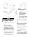
5. REMOVE CRATE -
A. Remove all crate fasteners. Lift off outside
container.
B. Remove all screws and brackets securing boiler to
skid.
C. Save two of the wooden slats from the container
sleeve for use in Steps D & E.
D. Tilt the boiler to one side and slide a wooden slat
under the two raised feet.
E. Tilt the boiler to the other side and slide another
wooden slat under the two raised feet.
F. Slide the boiler forward or backward off the skid
using the two wooden slats as runners.
6. Move boiler to permanent position.
7. PROVIDE CLEARANCE and AIR for COMBUS-
TION and VENTILATION.
WARNING
Adequate combustion and ventilation air must be
provided to assure proper combustion.
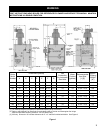
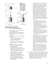
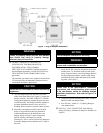
A. CLEARANCES
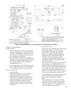
1. ALL INSTALLATIONS - Practical service
clearances must be considered (see Figure 1). A
minimum of 24" (6.0cm) from the left side and
front jacket panels is recommended for servicing
but may be reduced to minimum shown in
Figure 2. Subject to boiler and system piping,
left side clearance may be reduced to 1" (2.5cm)
if right side clearance is increased to 9"
(22.9cm).
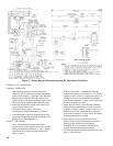
2. ALCOVE INSTALLATIONS - An alcove is
considered a closet as shown in Figure 2 less
front. Height clearance may be reduced to 27"
(68.6cm).
3. UNCONFINED SPACE (see denition,
paragraph (B) below) - Height clearance may be
reduced to 27" (68.6cm).
B. PROVIDE COMBUSTION AND VENTILATION
AIR in accordance with applicable provisions of
local building codes, or: U.S.A. - National Fuel
Gas Code, NFPA 54/ANSI Z223.1, Canada -
Natural and Propane Gas Installation Code, CAN/
CSA-B149.1.
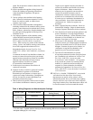
1. CLOSET INSTALLATIONS (conned space) in
a building of other than unusually tight
construction (see denition below), provide
combustion and ventilation air as shown in
Figure 2.
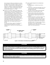
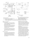
2. Installations other than closet in paragraph (1) :
a. Determine volume of space (boiler room).
Rooms communicating directly with space
(through openings not furnished with doors)
are considered part of space.