


20
e. Reconnect pilot tubing and check pipe and
ttings from meter to combination Gas
Valve for leaks using soap solution or other
approved method.
2. Electronic Ignition Models (Sufx I):
a. Turn "ON" electric switch serving boiler.
b. Open Manual Shut-off Valve upstream of
Combination Gas Valve.
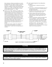
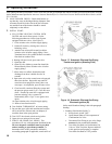
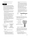
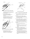
c. Loosen or remove Inlet Pressure Tap Plug in
Combination Gas Valve and when purging is
complete, tighten or replace plug. See Figure
19.
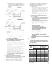
d. Check pipe and ttings from meter to
Combination Gas Valve using soap solution
or other approved methods.
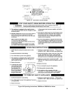
CAUTION
e. Test gas piping and connections between
Combination Gas Valve and manifold,
orices, and pilot piping for leaks after
boiler is operating. Use soap solution or
other approved method.
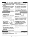
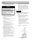
3. INSTRUCTIONS TO PUT THE BOILER IN
OPERATION.
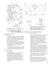
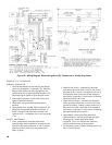
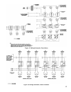
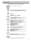
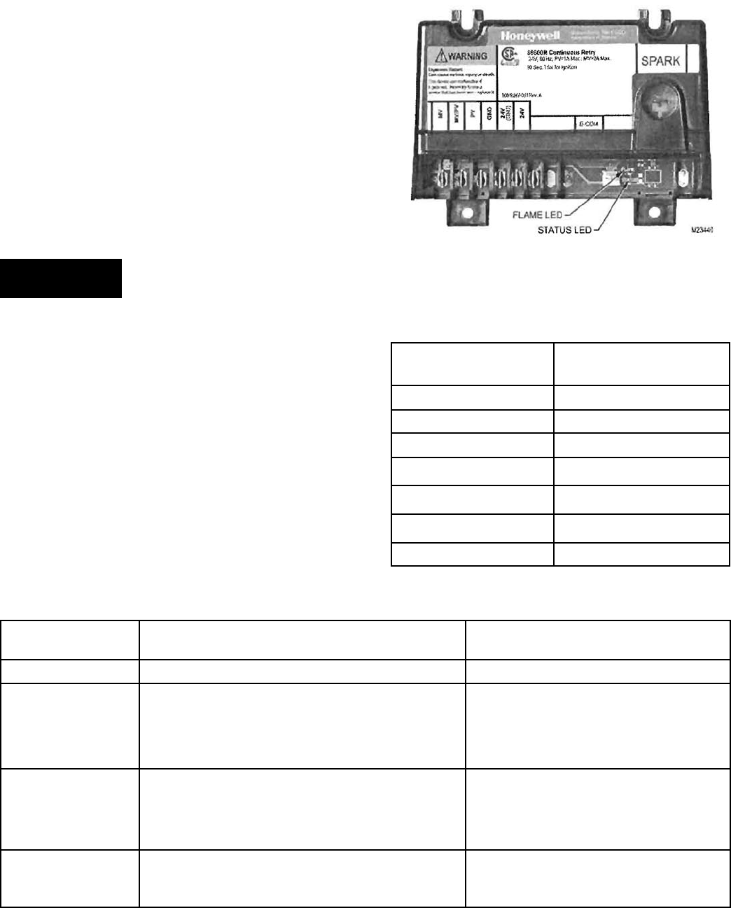
A. See Figure 20 for electronic ignition (EI).
Electronic Ignition Modules with LED indicators.
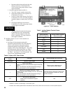
Table 5 cross-references the ignition module
terminal designations to the ignition terminal
numbers in the wiring ladder diagrams. The yellow
LED indicates the status of the ame, see Table 6.
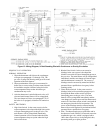
The green LED indicates the status of the system,
see Table 7. See Figure 21 for LED locations. See
Figure 28 for Troubleshooting Guide.
Figure 21: LED Locations
Ignition Module
Terminal Designation
Wiring Ladder Diagram
Terminal Number
MV 1
MV/PV 2
PV 3
GND 4
24V (GND) 5
24V 6
SPARK 9
Table 5: Ignition Module Terminal Cross-
Reference
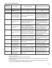
Yellow LED Flash
Code
a
Indicates Recommended Service Action
Heartbeat Normal Flame Signal N/A
2
Weak Flame Signal -
System will operate reliably but ame signal is less than
desired.
Note: This indication may ash temporarily during or
shortly after lightoff on some applications.
Perform routine maintenance to
assure optimum ame signal.
1
Marginal Flame Signal (less than 1.1 µA) -
System may not operate reliably over time. Service call
recommended.
Note: This indication may ash temporarily during or
shortly after lightoff on some applications.
Check gas supply, pilot burner, ame sense
wiring, contamination of ame rod, burner
ground connection.
OFF
No Flame or Flame Signal -
below minimum threshold for system
operation.
N/A
a
Flash Code Descriptions
- Heartbeat: Constant ½ second bright, ½ second dim cycles.
- The ash code number signies that the LED ashes X times at 2Hz, remains off for two seconds, and then repeats sequence.
Table 6: Yellow LED Flame Codes