


27
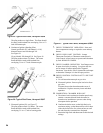
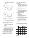
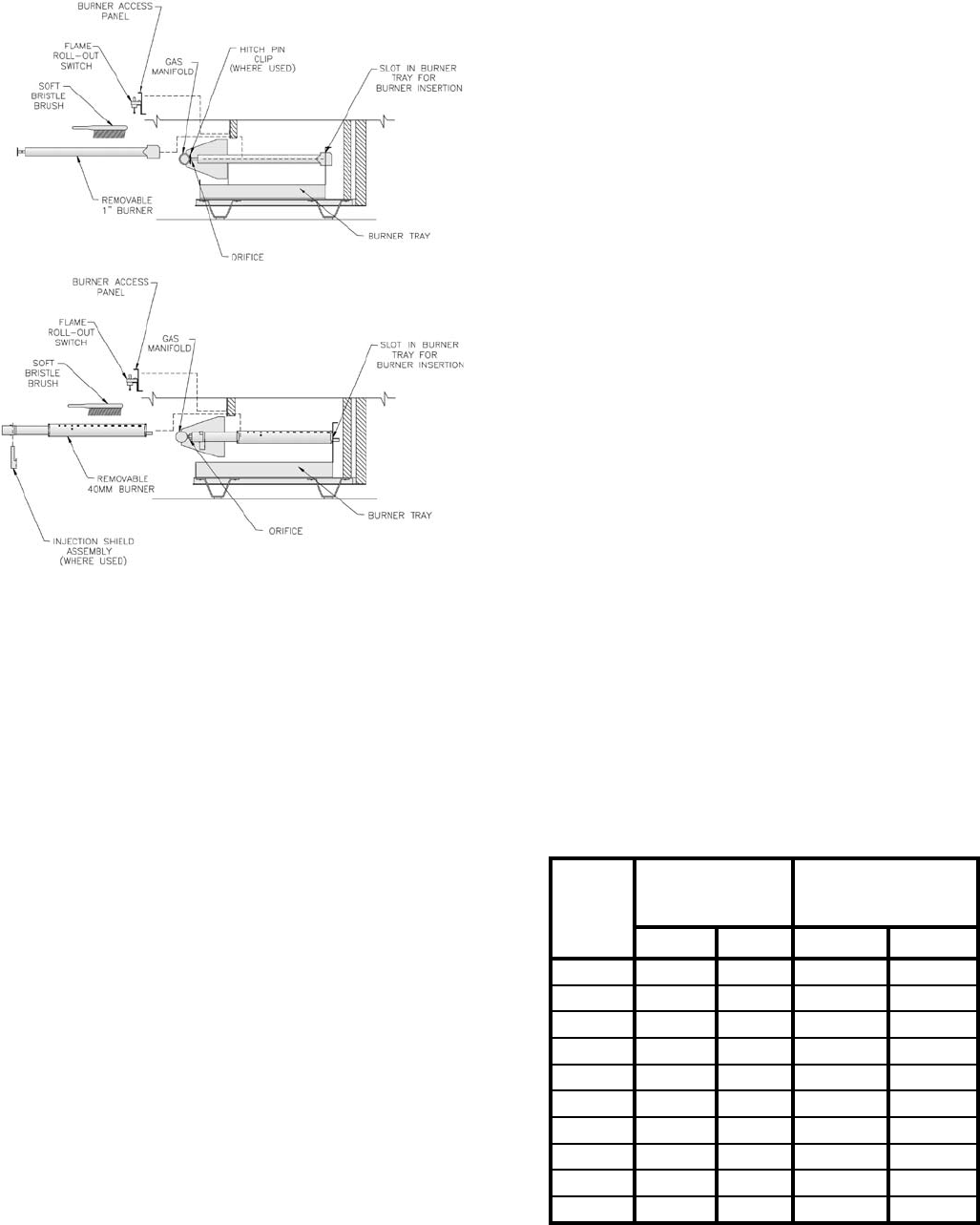
8. Hold burner at throat. Lift front of burner to
clear orice. Burner which holds pilot can only
be removed by lifting the burner adjacent to its
right rst.
Figure 30: Burner Cleaning and Installation
9. Brush top of burners with a soft bristle brush, see
Figure 30. Vacuum burners. Check orices to see
that drilled passageways are free of lint or dirt.
10. Vacuum tip of Pilot Burner.
B. CLEAN FIREBOX by vacuuming. Exercise care
not to disturb insulation inside the base.
C. INSTALL BURNERS by reversing procedure used
to remove burners. Make sure burner with pilot
assembly is in same location as original installation
- see Table 8.
Check burners to see that they are located properly
in slot at rear of burner tray, see Figure 30.
Reinstall injection shield assembly (40mm burners
only, where used) and burner access panel.
Reconnect ame roll-out switch wires, pilot gas
supply, thermocouple lead or pilot lead.
D. CHECK MAIN BURNER and PILOT FLAMES,
see procedure Section II Operating Instructions,
paragraphs 5 and 6.
5. CHECK ALL CONTROL AND DAMPER
OPERATION ANNUALLY see procedure in Section II
Operating Instructions, paragraphs 7 through 10.
6. REMOVAL OR REPLACEMENT OF PILOT
ASSEMBLY OR PILOT ASSEMBLY PARTS
If pilot assembly, thermocouple or pilot orice need
replacing, remove main burner with pilot using
procedure described in paragraph 4.
A. To replace orice:
1. Disconnect pilot tubing. The Honeywell Q350
pilot orices are insert type retained by the
compression tting. The Honeywell Q327 and
Q348A pilot orices are spud type screwed into
pilot burner. Replace with desired orice. See
Key No. 5B.
2. Reconnect pilot tubing and check for leaks.
B. To replace Honeywell Q309A thermocouple in
Q327 or Q350 pilot:
1. Loosen attachment nut securing thermocouple to
barrel of pilot burner. Disconnect other end at
combination gas valve.
2. Remove thermocouple and replace with equal.
C. To replace complete pilot assembly.
1. Remove machine screws holding pilot burner to
pilot bracket.
2. Disconnect pilot piping.
3. Disconnect all other leads to pilot.
4. Select pilot assembly with identical model
number, reconnect leads and pilot tubing -
resecure to pilot bracket.
D. To adjust or check spark gap between electrode and
hood on Honeywell Q348A pilot.
1. Use round wire gauge to check spark gap.
2. Spark gap should be 1/8 inch for optimum
performance.
E. Reinstall main burner following procedure described
in paragraph 4.
7. LUBRICATION
There are no parts requiring lubrication on the part of
the service technician or the User. Circulator bearings
are water lubricated.
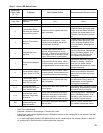
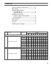
Table 8: Pilot Burner Location
1" Burner
40mm Burner
Boiler
Model
Main Burner with
Pilot Bracket *
Pilot Burner Located
Between Main
Burners *
1 Inch 40mm 1 Inch 40mm
202 1 1 1 & 2 ---
202X 1 1 1 & 2 1 & 2
203 1 1 1 & 2 1 & 2
204 2 2 2 & 3 2 & 3
205 3 2 3 & 4 2 & 3
206 4 3 4 & 5 3 & 4
207 6 3 6 & 7 3 & 4
208 7 4 7 & 8 4 & 5
209 8 4 8 & 9 4 & 5
210 9 5 9 & 10 5 & 6
* Main burners numbered left to right as viewed from
front of boiler.