


26
IV. Service
1. Inspection should be conducted annually. Service as
frequently as specied in paragraphs below. While
service or maintenance is being done, Electrical Power
and all Gas Supply to the Boiler must be "off".
CAUTION
Label all wires prior to disconnection when
servicing controls. Wiring errors can cause
improper and dangerous operation. Verify
proper operation after servicing.
ATTENTION. Au moment de l’entretien des
commandes, étiquetez tous les ls avant
de les débrancher. Les erreurs de câblage
peuvent nuire au bon fonctionnement et être
dangereuses.
S’assurer que l’appareil fonctionne
adéquatement une fois l’entretien terminé.
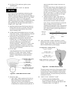
2. VENT SYSTEM. Vent system (see Figure 8 for typical
installation) should be checked annually for:
A. Obstructions.
B. Accumulations of soot.
C. Deterioration of vent pipe or vent accessories due to
condensation or other reasons.
D. Proper support - no sags, particularly in horizontal
runs.
E. Tightness of joints.
F. Proper vent damper operation - see Section II
Operating Instructions, paragraph 9.
G. Remove all accumulations of soot with wire brush
and vacuum, see Figure 29. Remove all
obstructions. Replace all deteriorated parts and
support properly. Seal all joints.
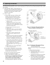
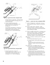
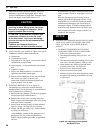
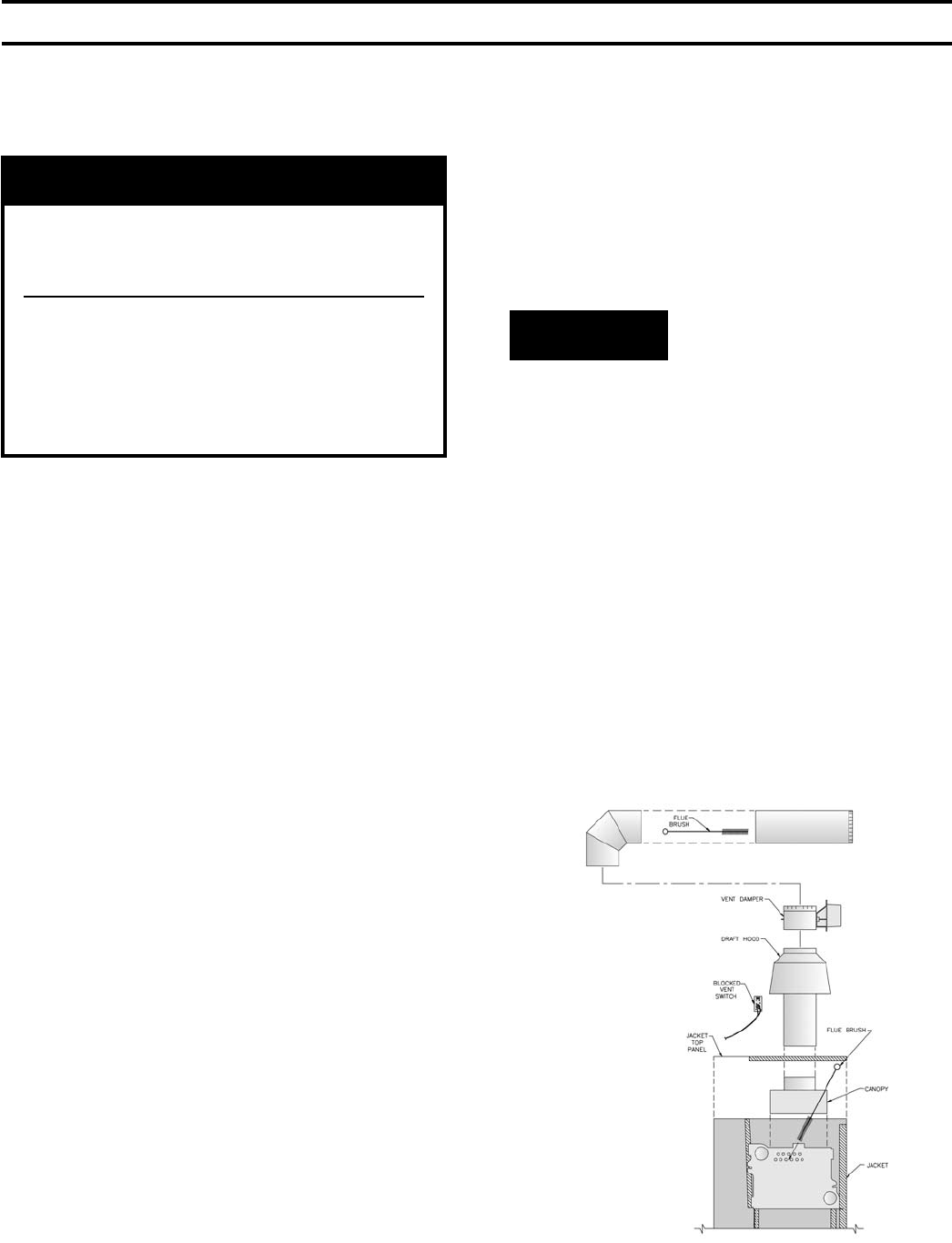
3. CLEANING BOILER FLUES, see Figure 29.
Flue passageways in the boiler sections should be
checked annually for any blockage or accumulation of
soot. To obtain access to ueways:
A. Remove vent pipe, damper (if boiler is so equipped),
blocked vent switch, and draft hood.
B. Remove sheet metal screws securing Jacket Top
Panel, lift panel and rotate about relief valve piping
until top of boiler is exposed.
C. Remove bolts securing Canopy to Boiler Sections.
Remove Canopy - ueways are now exposed.
D. Models with ue gas bafes only: Remove bafes
by lifting out of ueways.
Using ashlight, examine all ue passageways. If
passageways are free of soot and obstruction,
replace canopy (and ue gas bafes, if applicable),
and seal.
Reinstall Jacket Top Panel, draft hood, blocked vent
switch, damper (if boiler is so equipped), and vent
pipe.
If the ue passageways need cleaning, remove
burners as described in paragraph 4 below. Using
long handle wire or bristle ue brush and vacuum,
brush ueways thoroughly from top of boiler as
illustrated in Figure 29. Replace canopy and seal
with boiler putty. Reinstall Jacket Top Panel, draft
hood, blocked vent switch, damper (if boiler is so
equipped), and vent pipe.
NOTICE
4. BURNERS AND FIREBOX SHOULD BE CLEANED
ANNUALLY, AND IF NECESSARY ADJUSTED
ONCE A YEAR BY A QUALIFIED SERVICE
AGENCY.
A. TO REMOVE BURNERS FOR CLEANING,
CHANGING ORIFICE PLUGS, OR REPAIRS.
1. Remove the jacket front panel.
2. Disconnect pilot tubing at the gas valve. See
Figure 17.
3. Disconnect thermocouple (standing pilot) or pilot
lead wires (electronic ignition) at the gas valve.
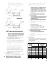
4. 40mm burners only. Remove injection shield
assembly, where used. See Figure 30.
5. Remove wires to ame roll-out switch.
6. Remove the burner access panel.
7. Mark the location of the pilot main burner on the
manifold if the marking on manifold is missing
or obliterated.
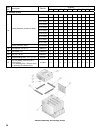
Figure 29: Cleaning of Vent System
and Boiler Flues