


16
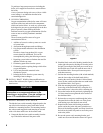
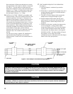
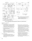
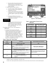
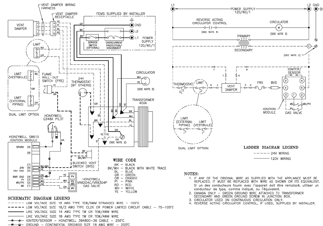
Figure 14: Wiring Diagram, Electronic Ignition (EI), Continuous or Gravity Circulation
SEQUENCE OF OPERATION
NORMAL OPERATION
1. When the thermostat calls for heat the vent damper
opens (see Paragraphs 17A through 17D). When the
damper blade reaches the fully open position, the
ignition module is energized opening the pilot valve
and energizing the igniter to ignite the pilot burner.
2. Sensor proves presence of pilot ame. Main valve
opens to ignite main burners.
3. The burners will operate until the thermostat is
satised.
4. When thermostat is satised, ignition module is de-
energized, extinguishing pilot and main ame. If
boiler is equipped with circulator, circulator will
continue to run. Vent damper closes (see Para-graph
17E).
SAFETY SHUTDOWN
1. Limit: Automatically interrupts main burner
operation when water temperature exceeds set point.
Maximum allowable temperature is 250°F. Normal
operation resumes when water temperature falls
below set point.
2. Blocked Vent Switch: Automatically interrupts
main burner operation when excessive vent system
blockage occurs. Control is a multiple use device. If
blocked vent switch is activated do not attempt to
place boiler in operation. Correct source of blockage
and reset blocked vent switch.
3. Flame Roll-out Switch: Automatically interrupts
boiler operation when ames or excessive heat are
present in vestibule. Control is single use device. If
ame roll-out switch is activated do not attempt to
place boiler in operation. Correct source of blockage
and replace ame roll-out switch.
4. Igniter/Sensor: senses pilot ame and causes
ignition module to turn off main burner and pilot
burner gas ow should pilot burner ame
extinguish. Five to six minutes after shutdown,
ignition module restarts ignition sequence.
5. For Electronic Ignition Trouble Shooting Guide, see
Page 25 of this manual.