


10
DANGER
Inspect existing chimney before installing boiler.
Failure to clean or replace perforated pipe or tile
lining will cause severe injury or death.
A. Vent installation shall be in accordance with local
building codes; or the local authority having
jurisdiction; or the National Fuel Gas Code, ANSI
Z223.1/NFPA 54; or the Standard for Chimneys,
Fireplaces, Vents, and Solid Fuel Burning
Appliances, ANSI/NFPA 211. Both of the
aforementioned standards, ANSI Z223.1 and ANSI/
NFPA 211, specify Type B and Type L double wall
metal vents and re clay tile lined masonry
chimneys as suitable chimney constructions for
Category I, draft hood equipped appliances, such as
this Series 2™ boiler. Both standards prohibit the
use of unlined masonry construction as a chimney,
with the exception in ANSI Z223.1/NFPA 54 that
"Where permitted by the authority having
jurisdiction, existing chimneys shall be permitted to
have their use continued when an appliance is
replaced by an appliance of similar type, input
rating, and efciency." ANSI/NFPA 211 prohibits
the use of single wall metal vent as a chimney, while
ANSI Z223.1 allows it under very restrictive
conditions. In Canada refer to the Natural Gas and
LP Installation Code, CAN/CSA-B149.1.
B. Do not connect into same leg of chimney serving an
open replace.
C. Inspect chimney for obstructions or restrictions and
remove. Clean chimney if necessary.
D. Vent pipe to chimney must not be smaller than outlet
on draft hood or damper. Although single wall vent
pipe may be used, Type B is recommended. The
venting system must be arranged so that only the
boiler is served by the damper device. Installation
per paragraph 12 complies with this provision.
E. Where two or more appliances vent into a common
vent, the area of the common vent should at least
equal the area of the largest vent plus 50% of the
area in the additional vents. Do not connect the vent
of this appliance into any portion of mechanical
draft system operating under positive pressure.
F. Vent pipe should have the greatest possible initial
rise above the draft hood consistent with the head
room available and the required clearance from
adjacent combustible building structure. Vent Pipe
should be installed above the bottom of chimney to
prevent blockage.
G. Vent pipe should slope upward from draft hood to
chimney not less than one inch in four feet. Doivent
présenter des tronçons horizontaux dont la pente
montante est d’au moins ¼ po par pied (21 mm/m)
entre la chaudière et l’évent. No portion of vent
pipe should run downward or have dips or sags.
Vent pipe must be securely supported. Les sections
horizontales doivent être supportées pour prévenir le
échissement.
H. Vent pipe must be inserted into but not beyond
inside wall of chimney liner. Seal tight between vent
pipe and chimney.
I. Do not install non-listed (AGA, CGA, CSA, ETL or
UL) vent damper or other obstruction in vent pipe.
WARNING
14. IF AN EXISTING BOILER IS REMOVED -
When an existing boiler is removed from a common
venting system, the common venting system is likely to
be too large for proper venting of the appliances
remaining to it.
At the time of removal of an existing boiler, the
following steps shall be followed with each
appliance remaining connected to the common
venting system placed in operation, while the other
appliances remaining connected to the common
venting system are not in operation:
A. Seal any unused openings in the common venting
system.
B. Visually inspect the venting system for proper size
and horizontal pitch and determine there is no
blockage or restriction, leakage, corrosion, and other
deciencies which could cause an unsafe condition.
C. Insofar as is practical, close all building doors and
windows and all doors between the space in which
the appliances remaining connected to the common
venting system are located and other spaces of the
building. Turn on clothes dryers and any appliance
not connected to the common venting system. Turn
on any exhaust fans, such as range-hoods and
bathroom exhausts, so they will operate at maximum
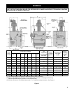
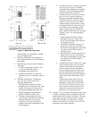
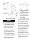
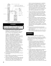
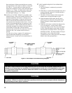
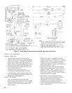
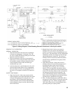
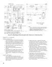
Figure 8: Typical Vent Installation