


GT-PG
44
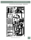
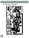
GT-PG (50YE) Series
Bryant: Whatever it Takes.
The water-to-re frig er ant heat exchanger and refrigerant
suction lines shall be insulated to prevent condensation at low liquid
tem per a tures.
Fan Motor and Blower
The fan shall be a direct drive centrifugal type with a dynamically
balanced wheel. The wheel and housing shall be designed for quiet,
low outlet velocity operation. The fan housing shall be of galvanized
steel construction and shall be re mov able from the unit without
dis con nect ing the supply air ductwork for servicing of the fan motor.
The fan motor shall be of 3-speed per ma nent ly split ca pac i tor
(PSC) type. The fan motor shall be high ef fi cien cy and provide high
static capability, and shall include three on-motor selectable air fl ow
options. An optional variable speed electronically commutated
(ECM) fan motor is available with permanently lubricated ball
bearing con struc tion, and it has no less than four op er a tion al speeds
online. The fan motor shall be isolated from the housing by rubber
grommets. The motor shall be permanently lu bri cat ed and have
thermal overload protection.
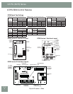
Electrical
CXM Control - A microprocessor-based compressor controller
shall be provided to monitor and control unit operation. The control
shall provide com pres sor and electric heater sequencing, high and
low pressure monitoring, fi eld selectable water and air coil low
temperature protection sensing, condensate overfl ow sensing, over/
under voltage monitoring, and unit performance sentinel (UPS). The
control shall also provide for water valve connection, a test mode,
short cycle protection, random start-up, as well as fault LED, fault
mem o ry, and intelligent fault retry.
The control shall employ quick attach harness as sem blies for low
voltage connections to the control board to aid in troubleshooting
or replacement. An integral terminal block with screw ter mi nals shall
be provided on the control for all fi eld low voltage connections. A
circuit breaker protected 75VA transformer shall be employed. Line
voltage box lugs shall be provided for unit wiring. Units shall have
knockouts for entrance of low and line voltage wiring. The fan motor
and control box shall be harness plug-connected for easy removal.
Residential models shall have a dual circut-breaker protected power
block for the connection of external fl ow controller pump module.
Piping
Supply and return water connections, as well as Hot Water
Generator (desuperheater) connections shall be 1" FPT brass swivel
fi ttings which provide a union and eliminate the need for pipe
wrenches and sealants when making fi eld con nec tions. A thread by
sweat fi tting shall be provided for connection to the water heating.
All water piping shall be in su lat ed to prevent condensation at low
liquid tem per a tures.
The condensate connection shall be a 3/4" PVC glue (socket) with
internal-trap (Vertical Models).
General
The water source heating/cooling units shall be vertical upfl ow air
discharge. Units shall be AHRI/ISO/ASHRAE 13256-1 (ground-
source closed-loop) per for mance cer ti fi ed and listed by a nationally
recognized safety-testing lab o ra to ry or agency. Each unit shall be
water run-tested at the factory. Each unit shall be pallet mounted and
shipped with appropriate protective packaging to help avoid damage
in transportation. The units shall be war rant ed by the man u fac tur er
against defects in materials and workmanship for a period of 10 years
on all parts, and 10 years on the compressor and refrigerant circuit
parts with a service labor allowance for fi ve years on refrigeration
components and two years on other parts. An optional extended
war ran ty is available for the GT-PG Series units, which increases the
labor allowances to 10 years on all parts. The water source units shall
be de signed to operate with entering fl uid tem per a ture between
20°F and 120°F.
Casing & Cabinet
The cabinet shall be fabricated from heavy-gauge galvanized steel and
painted with an epoxy powder coating. The interior shall be insulated
with 1/2" thick, multi-density, coated glass fi ber. Insulation in the air
handler section shall be foil backed for ease of cleaning. Two (vertical)
or one (horizontal) blower compartment and three compressor
compartment access panels shall be pro vid ed and shall be re mov able
with supply and return ductwork in place. The internal component
layout shall provide for major service with the unit in-place for
re strict ed access installations.
A duct collar (Field installed) shall be provided on the supply air
opening. 2" high effi ciency MERV11 pleated fi lters shall be provided
with each unit. Units shall have fi lter frames. The units shall have an
insulated divider panel between the air handling section and the
com pres sor section to minimize the transmission of compressor
noise, and to permit op er a tion al service testing without air bypass.
Units shall be supplied with left or right air inlet.
Refrigerant Circuit
All units shall contain Puron
®
(HFC-410A) sealed re frig er ant circuit
employing a hermetic motor-com pres sor, bidirectional thermal
expansion valve, fi nned tube tin plated air-to-refrigerant heat
exchanger, reversing valve, coaxial tube water-to-refrigerant heat
exchanger and service ports. An optional Hot Water Generator
(desuperheater) coil shall be provided.
Compressors shall be Copeland scroll type designed for heat pump
duty and mounted on dual level compressor vibration isolation.
Compressor motors shall be single phase PSC with internal over load
protection. A factory installed bidirectional fi lter drier shall be provided
on all models. The fi nned tube coil shall be sized for low-face velocity
and constructed of lanced aluminum fi ns bonded to rifl ed copper tubes
in a staggered pattern not less than three rows deep. Entire air coil
surface shall be tin-coated for corrosion protection.
The coaxial water-to-refrigerant heat exchangers shall be designed
for close approach temperatures and be con struct ed of a convoluted
copper (optional cu pro-n ick el) inner tube and a steel outer tube. The
thermal expansion valves shall provide proper superheat over the
entire fl uid temperature range with minimal “hunting”. The valve shall
operate bi-directionally without the use of check valves.
Engineering Guide Specifi cations