


Bryant Geothermal Heat Pump Systems
GT-PG
39
Residential Products Technical Guide
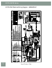
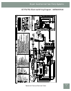
GT-PG ECM Control Features
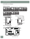
The ECM fan is controlled by an interface board that
converts thermostat inputs and fi eld selectable CFM
settings to signals used by the ECM motor controller.
Units manufactured before July 2005 have version I (P/N
69243707). Units manufactured between July 2005 and
May 11, 2009 have version II (P/N 17B0019N01). Fan
speeds are selected with jumpers for version I or via a
nine position DIP switch for version II and III. To take
full advantage of the ECM motor features, a multi-stage
thermostat should be used (2-stage heat/2-stage cool or
3-stage heat/2-stage cool).
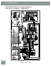
HFC-410A packaged units built after May 11, 2009 have
a ECM controllers version III (P/N 17B0034N01). This
controller includes logic and a relay to control the HWG
functions.
Note: Power must be off to the unit for at least three
seconds before the ECM motor will recognize a speed
change. The motor will recognize a change in the CFM
Adjust or dehumidifi cation mode settings while the unit
is powered.
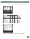
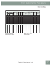
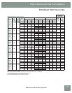
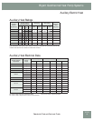
There are four different airfl ow settings from lowest airfl ow
rate (speed tap 1) to the highest airfl ow rate (speed tap 4).
The charts below indicate settings for both versions of the
ECM interface board, followed by detailed information for
each setting.
Cooling Settings: The cooling setting determines the
cooling (normal) CFM for all units with ECM motor.
Cooling (normal) setting is used when the unit is not in
dehumidifi cation mode. This setting also determines the
heating CFM for GT-G (50YC) units. Tap 1 is the lowest CFM
setting, while tap 4 is the highest CFM setting. To avoid air
coil freeze-up, tap 1 may not be used if the dehumidifi cation
mode is selected. Consult submittal data or specifi cations
catalog for the specifi c unit series and model to correlate
speed tap setting to airfl ow in CFM.
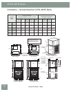
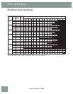
H
eating Settings
: The heating setting determines the
heating CFM for GT-PX (50YD) and GT-PG
(50YE) units.
This setting is not used for
GT-G (50YC)
units. Tap 1 is
the lowest CFM setting, while tap 4 is the highest CFM
setting. Consult submittal data or specifi cations catalog for
the specifi c unit series and model to correlate speed tap
setting to airfl ow in CFM.
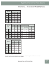
Auxiliary/Emergency Heat Settings: The auxiliary/
emergency heat setting determines the CFM when the unit
is in auxiliary heat or emergency heat mode. This setting
is used for residential units with internal electric heat.
When auxiliary electric heat is energized (i.e. compressor
and electric heat), the greater of the auxiliary/emergency
or heating setting will be used. A “G” (fan) signal must be
present from the thermostat for electric heat to operate.
Consult the submittal data or specifi cations catalog for the
specifi c unit series and model to correlate speed tap setting
to airfl ow in CFM.
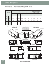
CFM Adjust Settings: The CFM adjust setting allows
four selections. The NORM setting is the factory default
position. The + or – settings adjust the airfl ow by +/- 15%.
The +/- settings are used to “fi ne tune” airfl ow adjustments.
The TEST setting runs the ECM motor at 70% torque, which
causes the motor to operate like a standard PSC motor, and
disables the CFM counter.
Dehumidifi cation Mode Settings: The dehumidifi cation
mode setting provides fi eld selection of humidity control.
When operating in the normal mode, the cooling airfl ow
settings are determined by the cooling tap setting above.
When dehumidifi cation is enabled there is a reduction in
airfl ow in cooling to increase the moisture removal of the
heat pump. Consult submittal data or specifi cations catalog
for the specifi c unit series and model to correlate speed
tap to airfl ow in CFM. The dehumidifi cation mode can be
enabled in two ways.
1. Constant Dehumidifi cation Mode: When the
dehumidifi cation mode is selected (via DIP switch or
jumper setting), the ECM motor will operate with a
multiplier applied to the cooling CFM settings (approx.
20-25% lower airfl ow). Any time the unit is running in
the cooling mode, it will operate at the lower airfl ow
to improve latent capacity. The “DEHUM” LED will be
illuminated at all times. Heating airfl ow is not affected.
NOTE: Do not select dehumidifi cation mode if cooling
setting is tap 1.
2. Automatic (Humidistat-controlled) Dehumidifi cation
Mode: When the dehumidifi cation mode is selected
(via DIP switch or jumper setting) AND a humidistat is
connected to terminal DH (version II) or HUM (version
I), the cooling airfl ow will only be reduced when the
humidistat senses that additional dehumidifi cation is
required. The DH (or HUM) terminal is reverse logic.
Therefore, a humidistat (not dehumidistat) is required.
The “DEHUM” LED will be illuminated only when
the humidistat is calling for dehumidifi cation mode.
Heating airfl ow is not affected. NOTE: Do not select
dehumidifi cation mode if cooling setting is tap 1.