


—9—
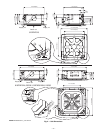
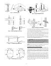
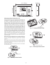
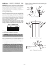
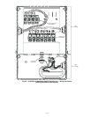
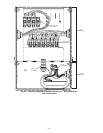
B. Mounting the Room Controller (Fig. 15-17)
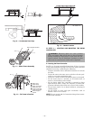
Unscrew the side fixing screw. Open the room controller rear
mounting base to expose the mounting holes. The base can
be removed to simplify mounting (snap apart carefully at
hinge to separate mounting base from the rest of the room
controller). Route the room controller wires through the
large hole in the mounting base. Level the mounting base
against the wall (for aesthetic value only, as the room con-
troller does not need to be level for proper operation) and
mark the wall through the two mounting holes. Drill two
3
/
16
in. mounting holes in the wall where marked. Secure the
mounting base correctly (UP) to the wall with the two screws
and two anchors provided, (additional anchoring holes are
available for more secure mounting if necessary) making
sure all wires extend through the hole in the mounting base.
Adjust the length and routing of each wire to reach the
proper terminal in the connector block on the mounting base,
with
1
/
4
in. of extra wire (strip only
1
/
4
in. of insulation from
each wire to prevent adjacent wires from shorting together
when connected).
Match and connect equipment wires to proper terminals in
the connector block. Both power and communication wires
must be connected correctly for proper room controller
operation.
Push any excess wire into the wall and against mounting
base. If the air sensor is being used on the room controller,
seal the hole in the wall to prevent air leaks. Leaks can
affect sensor operation.
Push the room controller snap hinge to the base and tighten
the side fixing screw.
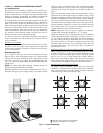
4-1/4" (108mm)
0mm)7("4/3-2
3/4"(20mm)
Fig. 14 — Room Controller Dimensions
Connection Cable
G
P
C
Fig. 16 — Locating the Connection Cable
Connection Cable
G
P
C
Fig. 17 — Connecting the Room Controller
Mounting screws
G
P
C
Fig. 15 — Mounting the Room Controller