


—17—
ETTES
SA
C LAB
OLG 619FNQ
R
ESNEDNOC ROOD
T
U
O
538QNF
NOTE 6
NOTE 5
Y
A
LPSI
D
RIA-
MT L
IOC-MT
"D" R
A
L
UDOM
BCP1 LORTNOC
REPPO
C
ERA
B
TCENNOCS
ID
T
INU OT
)DEDIVO
R
P
E
LBA
C ESU(
D
NG .PIUQE
V032/802
HP1
) 9ETON EES(
ROODTUO OT
TCENNOCSID TIN
U
7
E
T
O
N
DNG PIUQE
ETTESSAC O
T
E
TT
ESSAC OT
NOTE 4
8
E
TON
T
S
O
RFED RDTUO
E
TTESSAC OT
ETTESS
A
C
O
T
ETTE
S
SAC O
T
ETTESSAC OT
ETTESSAC
OT
ETTESSAC OT
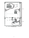
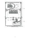
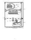
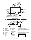
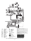
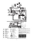
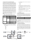
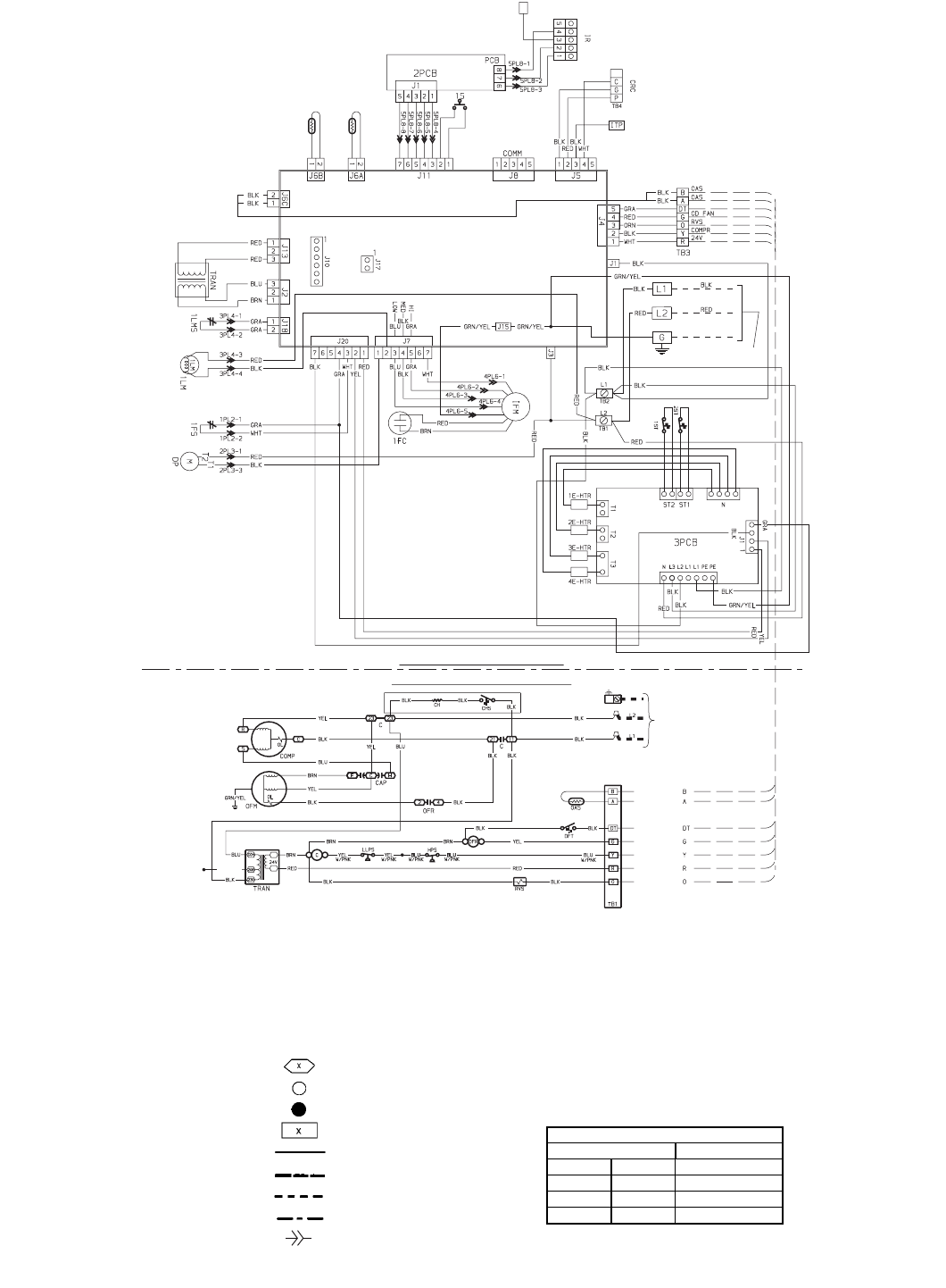
Fig. 26 — 619FNQ/538QNF Heat Pump System Wiring Diagram with Electric Heaters
LEGEND
1PCB — Main Control Printed
Circuit Board
2PCB — Display Board
3PCB — Printed Circuit Board for
Electric Heat
C—Contactor
CAP — Capacitor
CH — Crankcase Heater
CHS — Crankcase Heater Switch
COMP — Compressor
CRC — Carrier Room Controller
DFT — Defrost Thermostat
DP — Drain Pump
E-HTR — Electric Heater
EQUIP.
GND
— Equipment Ground
FC — Fan Capacitor
FS — Float Switch
GND — Ground
HPS — High Pressure Switch
IFM — Indoor Fan Motor
IR — Infrared
ITP — Indoor Test Point
LLPS — Liquid Low Pressure Switch
LM — Louver Motor
LMS — Louver Micro Switch
OAS — Outdoor Air Sensor
OFM — Outdoor Fan Motor
OFR — Outdoor Fan Relay
OL — Overload
RVS — Reversing Valve Solenoid
S—Emergency
ST — Safety Thermostat
TB — Terminal Block
TM — Sensor
TRAN — Tr an sforme r
Terminal (Marked)
Terminal (Unmarked)
Splice
Terminal Block
Factory Wiring
Field Control Wiring
Field Power Wiring
Accessory or Optional Wiring
Plug Connector
NOTES:
1. If any of the original wire furnished must be replaced, it must be
replaced with Type 90° C wire or its equivalent.
2. Wire in accordance with National Electrical Code (NEC) and local
codes.
3. Compressor and fan motors are protected by internal thermal
overloads.
4. Indoor unit transformer has internal 2A thermal fuse on the primary
side.
5. Infrared (IR) connection to be inserted on “J5” (replace the actual
factory-installed “CRC” connector) for IR option.
6. Terminal strip for Carrier Room Controller (CRC) connection.
7. Compressor crankcase heater installed on 538QNF035 and
538QNF030 only.
8. Outdoor unit transformer is factory wired for 230 v. For 208 v move the
black wire to the 208-v tap.
9. Use minimum 60° C wire for the field power wiring.
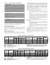
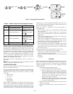
NOTE: All thermistors are identical.
THERMISTOR EQUIVALENCE
TEMPERATURE RESISTANCE
°F °C Ω
95 35 6,500
72 22 11,400
32 0 32,500