


—11—
V. STEP 5 — MAKE ELECTRICAL CONNECTIONS
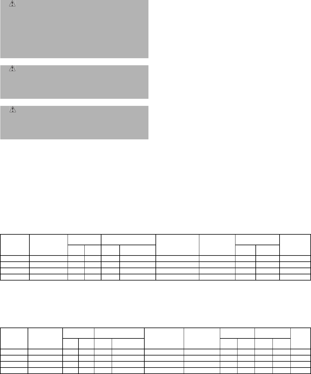
See Tables 6A and 6B for electrical information.
A. Units With Electric Heater
The unit is equipped with two thermostats: one with auto-
matic reset and one with manual (electric) reset that can be
reactivated by switching the power supply off and then
back on.
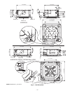
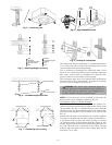
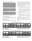
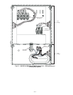
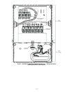
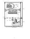
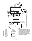
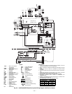
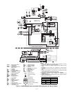
B. Power Wiring (Fig. 21-26)
The unit is factory wired for voltage shown on nameplate.
Provide adequate, fused disconnect switch within sight from
unit, readily accessible, but out of reach of children. Provi-
sion for locking the switch open (off) is advisable to prevent
power from being turned on while unit is being serviced. Dis-
connect switch, fuses, and field wiring must comply with the
NEC and local code requirements. Use copper wire only
between the disconnect switch and unit. Use minimum 60 C
wire for the field power connection.
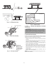
Remove the external box cover. Route the low voltage wires
from the outdoor unit to the indoor unit:
1. Place wiring through
7
/
8
in. knockouts on the left or
right hand side of external control box (low voltage
side).
2. Connect the R and Y wires to the 2 pin terminal block
for cooling only units (619FNF) and heat pump units
(619FNQ) that are matched to 538ENF outdoor units.
3. Connect the R, Y, O, G, DT, A, and B wires to the
(PGB-1) 1 terminal for 619FNQ indoor units matched
with 538QNF outdoor units.
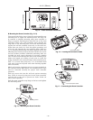
Route the line power leads from the indoor disconnect to the
fan coil unit.
1. Place wiring through
7
/
8
in. or 1
1
/
8
in. knockouts on
the left and on the right hand side of external control
box (high voltage side).
2. Connect L1 to the black wire and L2 to the red wire
using wire nuts and fix the ground wire between the
2 washers.
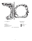
See Fig. 27 for a view of the internal control panel. The inter-
nal control panel can be accessed by opening the grille and
removing the metal cover attached by four screws.
NOTE: The internal control panel does not need to be
accessed during the installation process unless there is a
need for service.
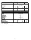
Table 6A — 619FNF Fan Coil Electrical Data
LEGEND *Permissible limits of the voltage range at which unit will operate
satisfactorily.
NOTE: In compliance with NEC requirements for multimotor and combina-
tion load equipment (refer to NEC Articles 430 and 440), the overcurrent pro-
tective device for the unit shall be fuse or equipped with a breaker.
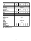
Table 6B — 619FNQ Fan Coil Electrical Data
LEGEND *Permissible limits of the voltage range at which unit will operate
satisfactorily.
NOTE: In compliance with NEC requirements for multimotor and combina-
tion load equipment (refer to NEC Articles 430 and 440), the overcurrent pro-
tective device for the unit shall be fuse or equipped with a breaker.
WARNING: Unit cabinet must have an uninter-
rupted, unbroken electrical ground to minimize the
possibility of personal injury if an electrical fault
should occur. This ground may consist of electrical
wire connected to unit ground lug in control compart-
ment, or conduit approved for electrical ground when
installed in accordance with NEC, and local electrical
codes. Failure to follow this warning could result in the
installer being liable for the personal injury of others.
CAUTION: Unit failure as a result of operation on
improper line voltage or excessive phase imbalance
constitutes abuse and may cause damage to electrical
components. Such operation would invalidate any
applicable Bryant warranty.
WARNING: Electrical shock can cause personal
injury and death. Shut off all power to this equipment
during installation. There may be more than one dis-
connect switch. Tag all disconnect locations to alert
others not to restore power until work is completed.
SYSTEM
SIZE
V-PH-Hz
VOLTAGE
RANGE*
FAN
CONDENSATE
PUMP FLA
LOUVER
MOTOR FLA
POWER
MIN WIRE
SIZE
AWG
Min Max FLA
Motor Power
(Watts)
MCA MOCP
018 208/230-1-60 187 253 0.55 120 0.06 0.01 0.8 15 14
024 208/230-1-60 187 253 0.50 110 0.06 0.01 0.7 15 14
030 208/230-1-60 187 253 0.95 210 0.06 0.01 1.3 15 14
036 208/230-1-60 187 253 0.95 210 0.06 0.01 1.3 15 14
AWG — American Wire Gage
FLA — Full Load Amps
MCA — Minimum Circuit Amps per NEC Section 430-24
MOCP — Maximum Overcurrent Protection
NEC — National Electrical Code
SYSTEM
SIZE
V-PH-Hz
VOLTAGE
RANGE*
FAN
CONDENSATE
PUMP FLA
LOUVER
MOTOR FLA
ELECTRIC
HEATERS
POWER
MIN
WIRE
SIZE
AWG
Min Max FLA
Motor Power
(Watts)
kW FLA MCA MOCP
018 208/230-1-60 187 253 0.50 110.0 0.06 0.01 3 12.5 16.3 20 12
024 208/230-1-60 187 253 0.50 110.0 0.06 0.01 3 12.5 16.3 20 12
030 208/230-1-60 187 253 0.95 210.0 0.06 0.01 3 12.5 16.9 20 12
036 208/230-1-60 187 253 0.95 210.0 0.06 0.01 3 12.5 16.9 20 12
AWG — American Wire Gage
FLA — Full Load Amps
MCA — Minimum Circuit Amps per NEC Section 430-24
MOCP — Maximum Overcurrent Protection
NEC — National Electrical Code