


—19—
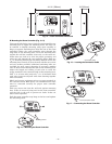
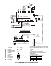
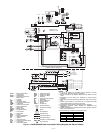
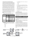
C. Wiring the Room Controller
The room controller is capable of controlling from 1 to 6 fan
coil units. The total run length of the wire connecting the
room controller to the fan coil units should be kept to under
500 feet. Wire the room controller to the unit using daisy
chain wiring. See Fig. 28. The room controller connects to
the receiver board connection on the electronic board inside
the unit.
Wiring the Power Connection to the Room Controller
The thermostat will be powered by unregulated nominal
12.5 volts DC (10V min to 20V max) which is provided by the
electronic board inside the unit. The power consumption will
be 50 mA 12.5 volts DC. For applications where more than
one fan coil unit is to be controlled, the fan coil unit closest to
the room controller will be the only one that supplies power
to the room controller. The control should be protected from
damage in case of accidental wiring of power, ground and
signal wiring occurs.
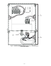
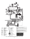
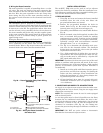
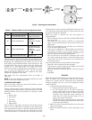
Wiring the Room Controller to the Indoor Unit
Loosen the screws of terminals P (DC Power), G (GROUND)
and C (SIGNAL) on the indoor unit and room controller
terminal blocks. Refer to Fig. 29 and connect the indoor unit
terminal block to the room controller terminal block.
INSTALLATION OPTIONS
The 619FNF, FNQ units can be used to cool an adjacent
room or for fresh-air ventilation. Plan the installation care-
fully. Measure carefully and follow acceptable building prac-
tices and the National Electric Code (NEC).
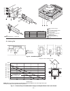
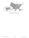
I. FRESH AIR INTAKE
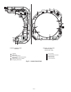
1. Using Fig. 30, locate and remove the factory-installed
insulation from the side of the unit where the
pre-punched knockouts are located.
2. Remove the pre-punched knockouts for fresh air
intake. Refer to Fig. 30. Be careful not to damage
internal parts such as the heat exchanger coil.
3. If installing a 619FNF018 unit, install baffle. Refer to
Fig. 30.
4. Install ductwork using field-supplied, insulated flex
duct, or insulated sheet metal suitable for working
temperatures up to 140 F. Conduits can be of flexible
polyester (with spiral core) or corrugated aluminum,
externally covered with anti-condensate material
(fiberglass from
1
/
4
in. to 1 in. thickness).
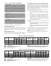
5. Use Fig. 31 to determine the allowable static pres-
sure loss for the ductwork airflow. The ductwork
design must not exceed this value or the job airflow
requirements will not be met.
6. Use a field-supplied fan if airflow does not meet job
requirements. The field-supplied fan motor for out-
side air intake must be controlled by a bipolar ON/
OFF switch with safety fuses.
IMPORTANT: Ventilated air must not exceed 10% of the total
airflow or problems with operation will result. If the venti-
lated air surpasses 10% of the total airflow, a field-supplied
primary air treatment system with separate deflectors is
recommended.
7. Install an air inlet grille with filter inspection port to
prevent dust and dirt from entering and fouling the
indoor unit heat exchanger. Filter installation also
makes the installation of a duct closing damper dur-
ing shutdown periods unnecessary.
8. All non-insulated ducts must be covered with anti-
condensate insulation (such as expanded neoprene,
1
/
4
in. thickness).
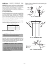
II. CONDITIONED AIR SUPPLY TO ADJACENT ROOM
Air supply to an adjacent room requires that the outlet corre-
sponding with the duct is closed, using the air supply outlet
obstruction accessory kit.
NOTE: The accessory kit cannot be used in units equipped
with an electric heater.
An air inlet grille must be fitted (if possible near the floor)
between the air conditioned room (where the unit is situ-
ated) and the adjacent room or, alternatively, the door must
be undercut, as shown in Fig. 30. The duct lengths can be
calculated in accordance with Fig. 30, also taking into
account the pressure drop through air diffusers and fresh air
filters.
IMPORTANT: DO NOT use active carbon or electrostatic
filter kits for ducts towards adjacent rooms.
P
G
C
P
G
C
Indoor unit
Room Controller
Diagram 1
Main electronic card
4 pins terminal block placed on external
control box
Wires supplied by the installer
Terminal block in the Room Controller
A
B
Red
Black
White
Remote connector
(J5) 5 pins
A
B
Fig. 29 — Wiring the Room Controller to
the Indoor Unit
REMOTE
FCU 6
FCU 3
FCU 2
FCU 1
Fig. 28 — Room Controller Daisy Chain Wiring
(Multidrop)