


—22—
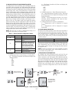
Table 8 — Modular Platform D Unit Configuration Values
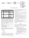
Only the current value being displayed is transmitted. Once
the Fan button is pressed, the room controller will switch to
displaying the configuration item number. To move to the
next setting, press the Mode button again and the “20” will
be displayed. Press the Up button and the display will
change to “21.” The Mode button will toggle the display
between the software configuration item number (i.e., “20,”
“21,” etc.) and the configuration value. The Up and Down
buttons will change either the item number or the value,
whichever is displayed at the time.
This mode will exit automatically after 30 seconds of
inactivity.
NOTE: If units are grouped to one room controller, all units
will have the same configuration value.
VI. SERVICE TEST MODE
Prior to start-up, conduct the Service Test mode to ensure
the unit is ready for start-up.
There is a hidden Service Test mode that is initiated through
a combination of button presses when the remote is off. The
following buttons need to be pressed, in sequence, within
6 seconds:
1. Down arrow
2. Fan button
3. Up arrow
4. Fan button
5. Mode button
Once in Service Test mode, the Service Test mode message
will be sent, and Sr will be displayed in the temperature
icons until the Down button is pressed. During Service Test
mode all the icons are off, and the only button that is active
is the Down button. To cancel Service Test mode, press the
Down button to send a message of Off mode to the unit. Ser-
vice Test mode automatically times out after 30 minutes and
the remote will operate normally.
When test mode is selected, the unit will operate as
described below:
• The Unit Status (Green) and Timer (Yellow) LEDs blink
every 2 seconds.
• The indoor fan will operate according to user-selected
speed. If user-selected speed is Auto, the fan will run in
High speed.
• If the unit is configured as an A/C Only unit, it will oper-
ate in cool mode with demand.
• If the unit is configured as a Heat Pump unit, the louver
will operate according to user-selected position. If user
selected louver is Auto, louver operates according to auto
heat or cool louver based on operating mode.
• The unit will run in cool mode for 3 minutes, then it will
run in heat mode for 2 minutes, or until the indoor coil is
greater than 104 F. The unit will run in cool mode until
test mode is exited.
Any of the following will cancel the Service Test mode:
• When the unit is turned off by the controller.
• If the power is cycled during the Test Mode, the unit will
return to its normal operating mode.
• After 30 minutes of receiving the last valid test request
message.
•Fail Mode.
START-UP
The following checks should be made before system start-up.
Refer to outdoor unit Installation, Start-Up, and Service
manual for system start-up instructions and refrigerant
charging methods. Be sure to use the refrigerant charge
shown in Table 3.
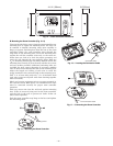
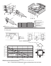
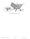
1. Check condensate drainage system.
a. Remove grille and frame from the unit.
b. On the opposite side of the drain connection,
insert a water bottle up into the fan coil unit and
fill drain pan. Refer to Fig. 34. Water must flow
regularly with condensate pump energized. If
water does not, check the pipe slope or see if
there are any pipe restrictions.
NOTE: The unit is equipped with a safety float
switch to deenergize the compressor if the drain
water level gets too high.
2. Make sure that all wiring connections are correct and
that they are tight.
3. Make sure that all barriers, covers, and panels are in
place.
ITEM VALUE COMMENT
20
1: Heat Pump
0: AC only (indoor unit with
or without electric heaters)
Unit Configuration
defaults to heat pump
21 1-199 in increments of 1
CCN Address of the unit.
Defaults to 1.
To display the hundreds,
push .
22 0-199 in increments of 1
Zone number -
Communications zone
the system is located in
Defaults to 0
To display the hundreds,
push .
24
0: Start in Off mode
1: Start in last active mode
Auto Restart
Defaults to “On”
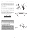
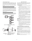
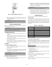
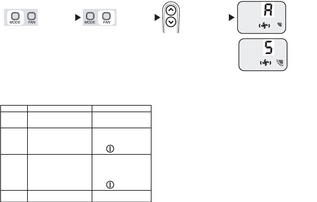
Room Controller
ON
up
down
Keep it pressed
for 5 seconds
To change
the value
Automatic
(AUTO)
Or
Continuous
movement
(swing)
Fig. 33 — Selecting the Louver Mode