


—7—
The condensate may be discharged at a maximum height of
7
7
/
8
in. above the unit, as long as the ascending tube is verti-
cal and aligned with the drainage flange.
If it is necessary to discharge the condensate from a level
above 7
7
/
8
in., install an auxiliary water discharge pump and
float valve. A float valve is recommended to stop the com-
pressor if there is a fault at the auxiliary pump.
The condensate pipe must be insulated with condensation
proof material such as polyurethane, propylene or neoprene
of
3
/
16
in. to
3
/
8
in. thickness. See Fig. 10.
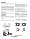
NOTE: If more than one unit is installed in the room, the
drain system can be designed as shown in Fig. 10.
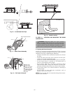
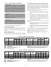
Installing the Grille and Frame Assembly
Carefully unpack the assembly and check for damage sus-
tained in transport. Attach the assembly to the unit by using
the two hooks. See Fig. 11. Tighten the four screws, link the
electrical connectors and insert the wires in the cable clamp.
Use the screws supplied to fix the frame in to position. See
Fig. 12.
Ensure that the frame is not distorted by excessive tighten-
ing, that it is aligned with the false ceiling and that there is
a seal between the air inlet and outlet. See Fig. 13. Gasket
“A” prevents return air from mixing with the supply air and
gasket “B” prevents the supply air from leaking into the ceil-
ing void. Once the unit is mounted in the ceiling, the gap
between the unit frame and the false ceiling must not be
more than
3
/
16
in. wide.
CAUTION: The drain tube extension must be
securely fastened to the condensate drain. Failure to
do so could result in condensate water dripping on to
the floor, which could cause personal injury.
Threaded hangers
"T" bar
(to be removed)
Supension Brackets
Supension Brackets
Threaded Hangers
T-Bar
T-Bar
Threaded Hangers
T-Bar
Washer
Threaded hangers
Washer
Nut
Nut
Nut
Wooden frame
Threaded hangers
Washers
Nut
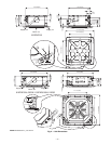
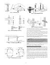
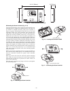
Fig. 4 — Positioning Unit
Fig. 5 — Attaching Hangers to Ceiling
Fig. 6 — Threaded Hangers and T Bar
Fig. 7 — Positioning Unit in Ceiling
False
Ceiling
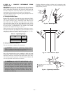
Spirit
Level
1“ to 1-3/16”
Indoor
Outdoor
3/16"
÷
3/8"
(5
÷
10 m
m
)
"4/
3-2
÷
"3
m 08/0
7(
m)
Fig. 8 — Align and Level the Unit
Fig. 9 — Drilling for Connections