


—6—
II. STEP 2 — LOCATING AND MOUNTING THE UNIT
A. Locating the Unit
Install the unit as centrally as possible in the room. The air-
flow
direction can be controlled by the remote control (where
used) or automatically, according to the unit operating mode
(cooling or heating). Controlling the airflow automatically
will ensure optimum distribution of the air in the room.
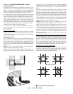
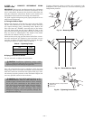
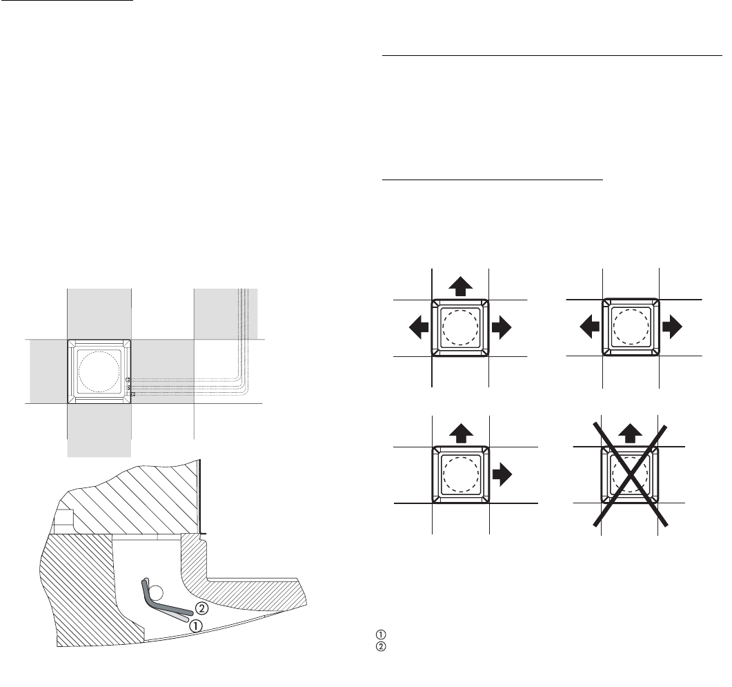
In Cooling mode, the louvers should be positioned so that the
air is directed towards the ceiling. Refer to Fig. 3. In Heating
mode, the louvers should be positioned so that the air is
directed toward the floor to prevent layers of hot air forming
close to the ceiling. Refer to Fig. 3. The louvers will be auto-
matically positioned when the louvers are set to Automatic
mode. Alternatively, the louvers can be placed in intermedi-
ate positions (with infrared remote accessory kit only) or
allowed to move continuously (Swing mode).
In order to allow easy and rapid installation and mainte-
nance, ensure that the unit is mounted in a location that is
easily accessible.
Restricting Air Outlets
A maximum of two air outlets can be restricted at one time.
See Fig. 3. The air supply outlet obstruction accessory kit
can be used to obstruct air outlets. Contact your local dealer
for more information.
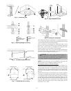
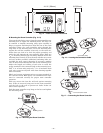
B. Mounting the Unit
Use a stacker to lift the unit to the installation location.
Refer to Fig. 4. If the mounting location is in a plaster board
ceiling, the maximum dimensions of the unit housing cutout
must not exceed 2 ft, 2 in. square for 619FNF018 units and
2 ft, 11 in. square for 619FNF024, 03036 and 619FNQ01824,
03036 units.
NOTE: In rooms with high humidity, brackets should be
insulated using self-adhesive insulation.
Mark the position of the hangers, refrigerant lines and con-
densate drain pipe, power supply cables and remote control
cable (see Fig. 2 for dimensions). The cardboard template
(supplied with the unit) may be used as a guide. Depending
on the type of ceiling, the hangers can be fixed as shown in
Fig. 5.
Once the threaded hangers have been positioned, do not
tighten the nuts. Insert the washers as shown in Fig. 5. First
position the refrigerant lines, which will be connected in the
Complete Refrigerant Piping Connections section. Remove
the “T” bar in the ceiling to facilitate installation. See Fig. 6.
Carefully lift the unit (without the frame) using the four sus-
pension brackets (or the four corners), and insert it into the
false ceiling. If the “T” bar cannot be removed from the ceil-
ing the unit may need to be tilted. See Fig. 7.
NOTE: Tilting the unit may only be carried out with false
ceilings with a minimum height of 11 ft-
13
/
16
inches.
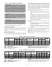
Align and level the unit by adjusting the nuts and locknuts
on the threaded hangers, maintaining a distance of 1 in. to
1
3
/
16
in. between the sheet metal body and the underside of
the false ceiling. See Fig. 8. Reposition the “T” bar and align
the unit in relation to the bar by tightening the nuts and
locknuts. After connection of the condensate drain line and
the refrigerant lines, carry out a final check to make sure
that the unit is level.
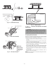
Drilling the Hole for Connection Pipes in the External Wall
After positioning the units and determining the connection
position, drill a 2
3
/
4
in. hole in the wall. The same hole can be
used as a condensate drain pipe conduit. The hole should
have a
3
/
16
in. to
3
/
8
in. slope toward the outside. Refer to
Fig. 9. Insert the plastic conduit. Pass the power connection
cables through the conduit. The power connection cables will
be connected in the Make Electrical Connections section.
Running the Condensate Drain Piping
To ensure correct condensate water flow, the drain pipe
should have a gradient of 2% without obstructions. Addition-
ally, a trap of at least 2 in. depth should be made to prevent
unpleasant odors from reaching the room.
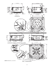
Max. 2 louvers closed
Heat pump: louver position for correct airflow.
Cooling: louver position for correct airflow.
Fig. 3 — Louver Positioning