


—21—
III. ROOM CONTROLLER CONFIGURATION SETUP
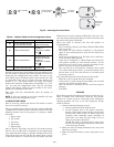
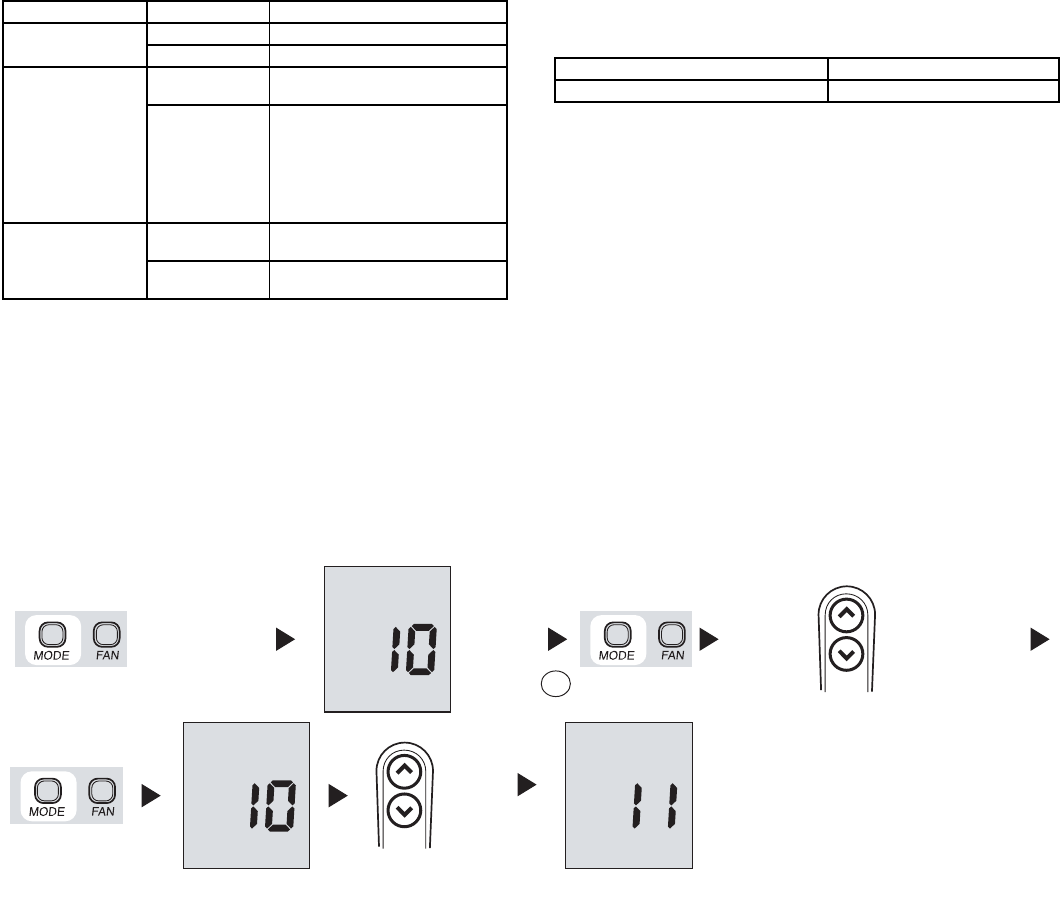
To configure the room controller, press the Mode button for
5 seconds. After 5 seconds, “10” will appear. This indicates
that the user is setting the first software configuration item.
To display the value of configuration item 10, press the Mode
button again. The value of the Heat/Cool vs Cooling only
remote configuration will be displayed along with the “Set
Temp” icon to indicate that the number displayed is the con-
figuration data. Refer to Table 7 for configuration values. To
change the Heat/Cool vs Cooling only remote Configuration,
press the Up and Down buttons. To move to the next setting,
press the Mode button again and the “10” will be displayed.
Press the up button and the display will change to “11.”
Refer to Fig. 32. The Mode button will toggle the display
between the items and the configuration value. The Up and
Down buttons will change either the index or the value,
whichever is displayed at the time. Press the Fan button to
exit the Configuration Setup Mode. This mode will exit auto-
matically after 10 seconds of inactivity. Once a configuration
value is changed, the last value displayed will be the new
configuration value for the room controller.
NOTE: The only way to abort a configuration change is to
change the value back to its original value.
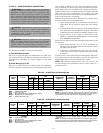
Table 7 — Room Controller Configuration Values
* Factory default.
1. Configuration Item 10: Heat Pump vs Cooling Mode
H — The Room Controller will allow and display the
following modes:
•Off
•Fan
•Auto
•Cool
•Dry
•Heat
C — The Room Controller will allow and display the
following modes:
•Off
•Fan
•Cool
•Dry
2. Configuration Item 11: Room Thermistor Override
On — Room Thermistor Override is active. Units will
be controlled to the air temperature displayed via the
Room Controller.
Of (Off) — Room Thermistor Override is not active.
All units will be controlled to the room air ther-
mistors located on the units.
3. Configuration Item 12: Celsius vs Fahrenheit
C — Temperatures will be displayed in degrees
Celsius.
F — Temperatures will be displayed in degrees
Fahrenheit.
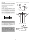
IV. LOUVER MODE SELECTION
To enter louver mode selection, ensure the room controller is
on and then press the Fan button for 5 seconds. After 5 sec-
onds, the selected louver setting will be displayed. Press the
up and down arrows to modify the louver setting between
swing and auto. Refer to Fig. 33. The two settings will be dis-
played as follows:
The fan icon will also be displayed in the louver mode. Press
Fan button to exit the Louver Mode selection. This mode will
exit automatically after 10 seconds of inactivity. The only
way to abort a louver change is to change the value back to
its original value.
NOTE: If units are grouped to one room controller, all units
will have the same louver value. Louver Mode selection is
not available during OFF mode.
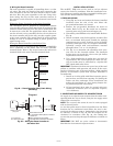
V. MAIN BOARD CONFIGURATION
To configure the main electronic board, push the Up and
Down arrows for 5 seconds while the room controller is off.
After 5 seconds, a “20” will appear. This indicates that the
user is setting the first software configuration item. To check
the value of configuration item “20,” press the Mode button.
The value for the Heat Pump/AC Only configuration will be
displayed. To change the value, use the Up and Down
buttons. Once the desired value is selected, press the Fan
button to send that configuration data to the unit. Refer to
Table 8.
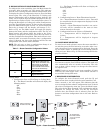
ITEM VALUE DESCRIPTION
10
H* Heat/Cool Remote
C Cooling Only Remote
11
On
Room Thermistor Override
Active.
Of*
Control and display room air
temperature at the room con-
troller. Room Thermistor Over-
ride Inactive. Do not display
room air temperature at the
room controller and control to
unit room air thermistor(s).
12
C*
Temperatures displayed in
degrees Celsius.
F
Temperatures displayed in
degrees Fahrenheit.
S with Swing Louver Icon Represents the swing louver
A with Auto Louver Icon Represents the auto louver
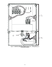
Keep it pressed for
at least 5 seconds
Check the
value
Change the
value
up
down
Next
item
up
down
To check/change
the values of items
11 and 12 go back
to point A
A
Fig. 32 — Room Controller Configuration Steps