


—67—
XII. FLUE GAS PASSAGEWAYS
To inspect the flue collector box and upper areas of the heat
exchanger:
1. Remove the combustion blower wheel and motor
assembly according to directions in Combustion-Air
Blower section below.
2. Remove the flue cover to inspect the heat exchanger.
3. Clean all surfaces as required using a wire brush.
XIII. COMBUSTION-AIR BLOWER
Clean seasonally to assure proper airflow and heating effi-
ciency. Inspect blower wheel every fall and periodically dur-
ing heating season. For the first heating season, inspect
blower wheel bimonthly to determine proper cleaning
frequency.
To inspect blower wheel, shine a flashlight into draft hood
opening. If cleaning is required, remove motor and wheel as
follows:
1. Slide burner access panel out.
2. Remove the 6 screws that attach induced-draft motor
housing to vestibule plate (Fig. 49).
3. The blower wheel can be cleaned at this point. If
additional cleaning is required, continue with Steps 4
and 5.
4. To remove blower from the motor shaft, remove
2 setscrews.
5. To remove motor, remove the 4 screws that hold
blower housing to mounting plate. Remove the motor
cooling fan by removing one setscrew. Then remove
nuts that hold motor to mounting plate.
6. To reinstall, reverse the procedure outlined above.
XIV. LIMIT SWITCH
Remove blower access panel (Fig. 1A and 1B). Limit switch is
located on the fan deck. Verify operation of limit by tempo-
rarily blocking return air until limit trips.
XV. BURNER IGNITION
Unit is equipped with a direct spark ignition 100% lockout
system. Integrated Gas Unit Controller (IGC) is located in
the control box (Fig. 11). Module contains a self-diagnostic
LED. A single LED on the IGC provides a visual display of
operational or sequential problems when the power supply is
interrupted. When a break in power occurs, the module will
be reset (resulting in a loss of fault history) and the indoor
(evaporator) fan ON/OFF times will be reset. For additional
information, refer to the Start-Up, Heating section on
page 51. The LED error code can be observed through the
viewport. See Fig. 11. During servicing refer to the label on
the control box cover or Table 36 for an explanation of LED
error code descriptions.
If lockout occurs, unit may be adjusted by interrupting
power supply to unit for at least 5 seconds.
XVI. MAIN BURNERS
At the beginning of each heating season, inspect for deterio-
ration, blockage due to corrosion or other causes. Observe
the main burner flames and replace burners if necessary.
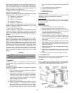
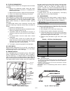
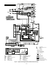
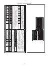
A. Removal and Replacement of Gas Train (Fig. 49 and 50)
1. Shut off manual gas valve.
2. Shut off power to unit and install lockout tag.
3. Slide out burner section side panel (not shown).
4. Disconnect gas piping at unit gas valve using backup
wrench on the flats of the valve body where the gas
pipe enters the gas valve. See Fig. 49.
5. Remove wires connected to gas valve. Mark each
wire.
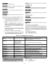
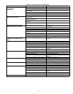
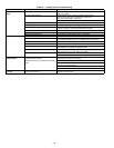
Table 36 — LED Error Code Description*
LEGEND
LED — Light-Emitting Diode
*A 3-second pause exists between LED error code flashes. If more
than one error code exists, all applicable codes will be displayed in
numerical sequence.
†Indicates a code that is not an error. The unit will continue to operate
when this code is displayed.
IMPORTANT: Refer to Troubleshooting Tables 38-40 for additional
information.
CAUTION: When working on gas train, do not hit
or plug orifice spuds.
LED INDICATION ERROR CODE DESCRIPTION
ON Normal Operation
OFF Hardware Failure
1Flash† Evaporator Fan On/Off Delay Modified
2Flashes Limit Switch Fault
3Flashes Flame Sense Fault
4Flashes 4 Consecutive Limit Switch Faults
5Flashes Ignition Lockout Fault
6Flashes Induced-Draft Motor Fault
7Flashes Rollout Switch Fault
8Flashes Internal Control Fault
9Flashes Software Lockout
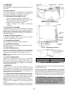
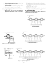
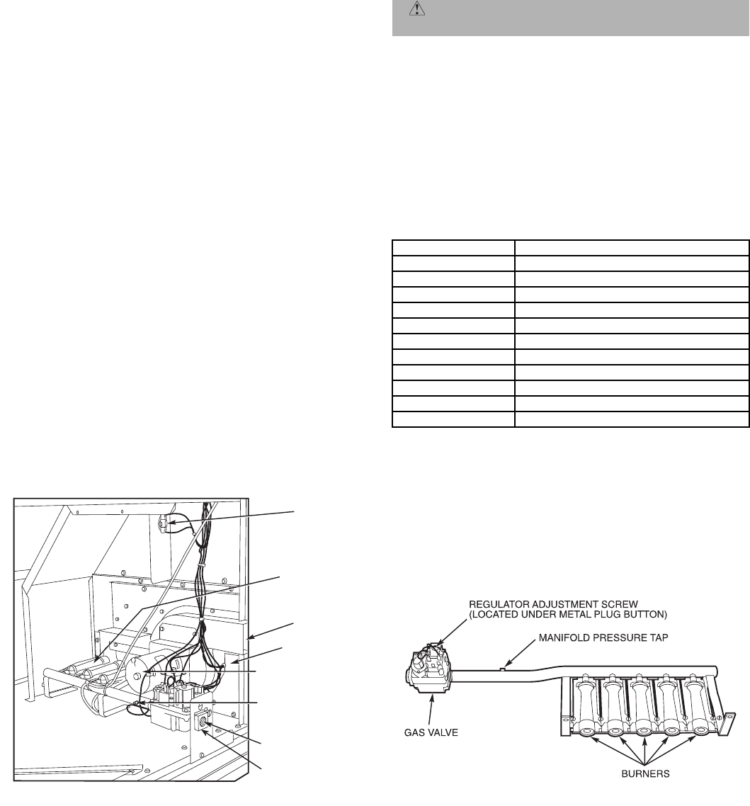
Fig. 50 — Burner Tray Details
BURNER
SECTION
ROLLOUT
SWITCH
INDUCED-DRAFT
MOTOR
FLUE
EXHAUST
FLUE
EXHAUST
VESTIBULE
PLATE
MANIFOLD
PRESSURE TAP
GAS VALVE
GAS VALVE
FLATS
Fig. 49 — Burner Section Details