


—22—
The user can read the value of the sensor using the Read
mode, described in the EconoMi$er+ Controller section.
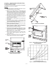
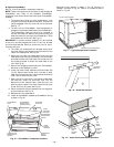
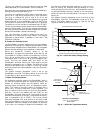
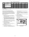
Mount the return air temperature sensor on the EconoMi$er+,
through pre-punched holes. See Fig. 27.
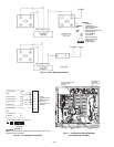
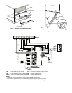
The return air temperature (RAT) sensor is provided with a
2-wire, 42-in. long wiring harness with a 2-pin connector.
The plug is installed on pins 5 and 6 on J3 of the
EconoMi$er+ controller. The pins are labeled with a ground
symbol and RAT on the EconoMi$er+ controller. See Fig. 22.
The red wire of the harness is connected to pin 5 (ground).
The black wire of the harness is connected to pin 6 (RAT).
The wiring harness should be routed from the EconoMi$er+
controller to the sensor. The controller compares the temper-
atures of the two airstreams, chooses the best one, and mod-
ulates the EconoMi$er+ actuator accordingly.
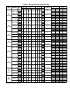
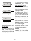
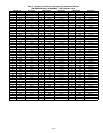
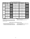
This 10K thermistor is used to measure the return air
temperature vs. resistance curve, per Table 5. The range of
temperature measurement is between 0° and 158 F. See
Table 6 for resolution.
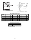
K. Outdoor Air Humidity Sensor
The EconoMi$er+ controller accepts input from the accessory
outdoor air humidity sensor in addition to the outdoor air tem-
perature sensor shipped with the EconoMi$er+. By using both
sensors, the total enthalpy of the outside air is calculated.
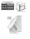
Mount the outdoor-air humidity sensor in to the
EconoMi$er+, through the pre-punched holes. See Fig. 28.
The outdoor-air humidity sensor is provided with a 2-wire,
42-in. wiring harness with a 2-pin connector. The plug is
installed on pins 11 and 12 on J3 of the EconoMi$er+ con-
troller. The pins are labeled ORH and VREF on the
EconoMi$er+ controller. See Fig. 22. The orange wire of the
harness is connected to pin 11 (ORH). The blue wire of the
harness is connected to pin 12 (VREF). The wiring harness
should be routed from the EconoMi$er+ controller to the sen-
sor location.
The outdoor enthalpy changeover curve is set at the
EconoMi$er+ controller. The factory default is curve “A.” See
Fig. 29. See Fig. 30 for Sensor Curve vs. Humidity.
L. Indoor Air Humidity Sensor
For differential enthalpy sensing, the EconoMi$er+ control-
ler uses the standard outdoor air temperature sensor, the
outdoor air humidity sensor, and the optional indoor air
humidity sensor, an optional return air temperature sensor
(RAT). The indoor-air humidity sensor is provided with a
2-wire, 42-in. wiring harness with a 2-pin connector. The
plug is installed on pins 8 and 9 on J3 of the EconoMi$er+
controller. The pins are labeled IRH and VREF on the
EconoMi$er+ controller. See Fig. 22. The orange wire of the
harness is connected to pin 8 (IRH). The blue wire of the har-
ness is connected to pin 9 (VREF). The wiring harness
should be extended with wires and wire nuts and routed
from the EconoMi$er+ controller to the sensor location. The
EconoMi$er+ controller compares the outdoor air enthalpy
to the return air enthalpy to determine EconoMi$er+ use.
The controller selects the lower enthalpy air (return or out-
door) for cooling. For example, when the outdoor air has a
lower enthalpy than the return air, the EconoMi$er+ control-
ler opens the damper to bring in outdoor air for free cooling.
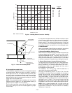
Mount the return-air humidity sensor in the return-air duct.
See Fig. 31.
The outdoor enthalpy changeover curve is set with at the
EconoMi$er+ controller. The selectable curves are A, B, C,
and D. The factory default is curve “A.” See Fig. 29. See
Fig. 30 for Sensor Curve vs. Humidity.
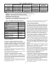
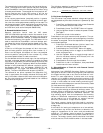
0
1000
2000
3000
4000
5000
6000
2345678
800 ppm
900 ppm
1000 ppm
1100 ppm
RANGE CONFIGURATION (ppm)
DAMPER VOLTAGE FOR MAX VENTILATION RATE
CO SENSOR MAX RANGE SETTING
2
ECONOMI$ER+ CONTROLLER
ACTUATOR
RETURN AIR
TEMP SENSOR
(HIDDEN)
HOOD
GROMMET
CURB
VERTICAL ECONOMI$ER+
(3 TO 12 1/2 TON UNITS)
(SIDE VIEW)
INDOOR AIR
HUMIDITY SENSOR
Fig. 26 — Indoor Air Quality Voltage Setting
Fig. 27 — Return Air Temperature Sensor