—53—
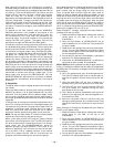
tens digit and the DS4 LED will then display the ones digit.
For example to display 54, the DS3 LED will flash 1 group of
5 at a high flash rate to indicate 50, and then follow with 4
flashes (DS4) at 1-second intervals to complete the display of
the number 54.
NOTE: Do not try to count the “5 Fast Flashes” individually,
but instead count how many groups of 5 flashes were
displayed. In this case, 1 group of 5 flashes, plus the 4 flashes
at 1 second results in the value of 54.
To read the display again, push the READ/ADJUST (#1) but-
ton and the sequence will repeat as many times as needed.
To advance to the next setup point, push the ADVANCE/
MANUAL (#2) button. The controller will cycle through all
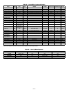
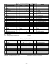
the setup channels (Table 34) and then the I/O channels
(Table 35) and then back to the first setup channel.
NOTE: The user can only advance forward, not reset to #1 or go
backwards. Cycling the EconoMi$er+ power will reset the item
number (but not the item value) to item #1.
In the Read mode for setup variables, the LEDs will not turn
on steady; the LEDs will always flash. Steady-on indicators
are reserved for the configuration modes. No data is modified
in the Read mode. The controller will always remain at the
last read number even if reset back to normal operation.
NOTE: To enter another mode, the user first must exit the
Read mode.
If no button is pushed in 10 minutes, Read mode will auto-
matically be exited. Also, if the READ/ADJUST (#1) and
ADVANCE/MANUAL (#2) buttons are pushed and held for
more than 3 seconds, then Read mode will be exited to Run
mode. While in the Read mode, the controller will continue to
operate with normal unit control.
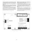
Y1
Y2
G
OCC
24V
1
J1
5
Y1 (cool 1)
Y2 (cool 2)
G (fan)
OCC
24 VAC
THERMOSTAT INPUTS
Occupied/unoccupied
I/O support dry circuit
contact (min 24 mA I)
POWER
SUPPLY
2-10 VDC
ECONOMIZER
CONTROL
J2
1
5
CNT
24V
24V
24 VAC
24 VAC
Control
SAT
OAT
RAT
IRH
VRF
ORH
VRF
IAQ
MIN
VRF
IAQ (4-20ma)
min (10K pot)
ORH (4-20 ma)
Vref
Vref
Vref
IRH (4-20 ma)
RAT (10k thermistor)
OAT (10k thermistor)
SAT (10k thermistor)
J3
1
17
ANALOG INPUTS
4-20 mAexternal powered between signal and ground
4-20 mAloop powered between 24 VDC and signal
Relays rated at 24 VAC 3A
and traces for 8A.
NOTE: For 1 and 2 stage
cooling, 2 stages of power
exhaust will be used.
For 3 cooling stages, only 1
stage of power exhaust will be
used, and for 4 stages no power
exhaust will be controlled
directly by the control.
OUTPUT RELAYS
C1
C2
24V
24V
24V
C3
C4
24 VAC
24 VAC
24 VAC
CP1
CP2
EX2/CP3
EX1/CP4
J4
READ/
ADJUST
ADVANCE
MANUAL
DS1 DS2
SETPOINT DISPLAY
DS3
DS4
date or serial no
RED
YELLOW
GREEN
PUSH BUTTONS
#1
#2
Fig. 36 — EconoMi$er+ Controller Board


