


—62—
II. LUBRICATION
A. Compressors
Each compressor is charged with the correct amount of oil at
the factory.
B. Fan-Motor Bearings
Fan-motor bearings are of the permanently lubricated type.
No further lubrication is required. No lubrication of
condenser-fan or evaporator-fan motors is required.
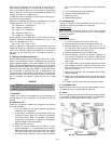
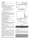
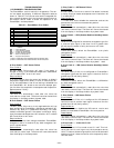
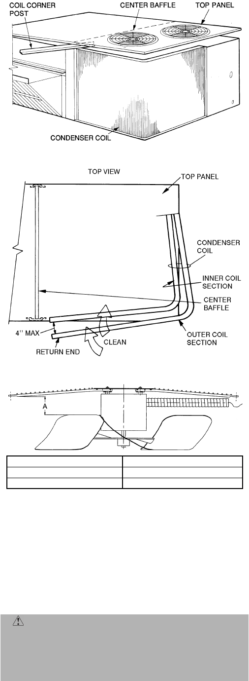
III. CONDENSER FAN ADJUSTMENT (Fig. 40)
1. Shut off unit power supply and tag disconnect.
2. Remove condenser-fan assembly (grille, motor, motor
cover, and fan) and loosen fan hub setscrews.
3. Adjust fan height as shown in Fig. 40.
4. Tighten setscrews and replace condenser-fan
assembly.
IV. BLOWER BELT ADJUSTMENT
Inspect blower belt for wear, proper belt tension, and pulley
alignment as conditions require or at the beginning of each
heating and air conditioning season. Refer to Step 9 —
Adjust Evaporator Fan Speed on page 27 for adjustment and
alignment procedures.
V. MANUAL OUTDOOR-AIR DAMPER
If outdoor-air damper blade is required, see Manual
Outdoor-Air Damper section on page 17.
VI. ECONOMIZER ADJUSTMENT
Refer to Optional EconoMi$er+ section on page 18.
VII. CONDENSER COIL GRILLE
Condenser coil grille is shipped factory-installed. No adjust-
ments are required.
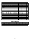
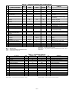
VIII. HIGH-PRESSURE SWITCH
Located on the compressor’s hot gas line is a high-pressure
switch. This switch opens at 428 psig and closes at 320 psig.
No adjustment is necessary. Refer to Tables 1A and 1B.
NOTE: There is no Schrader core in the valve below the high-
pressure switch.
IX. LOSS-OF-CHARGE SWITCH
Located on the condenser’s liquid line is a low-pressure
switch which functions as a loss-of-charge switch. This
switch contains a Schrader core depressor. This switch opens
at 7 psig and closes at 22 psig. No adjustment is necessary.
Refer to Tables 1A and 1B.
X. FREEZESTAT
Located on the “hair pin” end of the evaporator coil is a
bimetal temperature sensing switch. This switch protects
the evaporator coil from freeze-up due to lack of airflow. The
switch opens at 30 F and closes at 45 F. No adjustment is
necessary. Refer to Tables 1A and 1B.
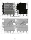
XI. CHECKING AND ADJUSTING REFRIGERANT CHARGE
The refrigerant system is fully charged with R-22 refriger-
ant, tested, and factory-sealed. Unit must operate in Cooling
mode a minimum of 10 minutes before checking charge.
NOTE: Adjustment of the refrigerant charge is not required
unless the unit is suspected of not having the proper R-22
charge.
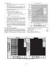
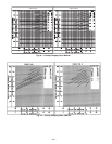
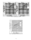
A superheat charging chart is attached to the outside of the
service access panel. The chart includes the required suction
line temperature at given suction line pressures and outdoor
ambient temperatures.
An accurate superheat, thermocouple-type or thermistor-
type thermometer, and a gage manifold are required when
using the superheat charging method for evaluating the unit
charge. Do not use mercury or small dial-type thermometers
because they are not adequate for this type of measurement.
CAUTION: When evaluating the refrigerant
charge, an indicated adjustment to the specified fac-
tory charge must always be very minimal. If a substan-
tial adjustment is indicated, an abnormal condition
exists somewhere in the cooling system, such as insuf-
ficient airflow across either coil or both coils.
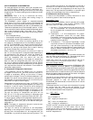
Fig. 38 — Propping Up Top Panel
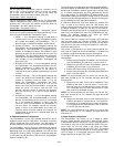
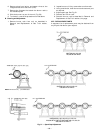
Fig. 39 — Separating Coil Sections
Fig. 40 — Condenser-Fan Adjustment
580F UNIT VOLTAGE FAN HEIGHT “A” (in.)
208/230 V 2.75
460 V and 575 V 3.50