—16—
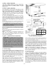
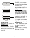
INTEGRATED
GAS UNIT
CONTROLLER
(IGC)
RACEWAY
UNIT LOW VOLTAGE
CONNECTION
BOARD
COMPRESSOR
NO.1
COMPRESSOR
NO. 2
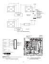
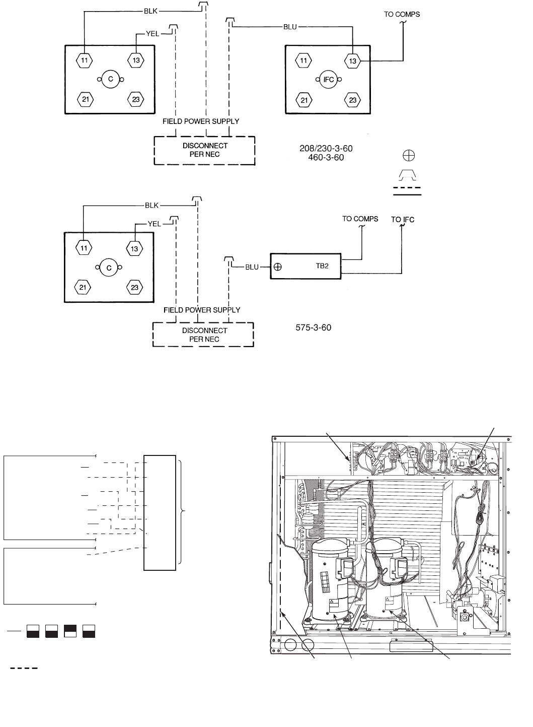
Fig. 9 — Power Wiring Connections
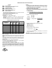
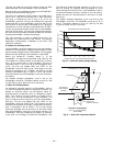
LEGEND
C—Contactor
COMPS — Compressors
IFC — Indoor (Evaporator)
Fan Contactor
NEC — National Electrical Code
TB — Terminal Block
Terminal Block
Connection
Splice Connection
(Factory Supplied)
Field Wiring
Factory Wiring
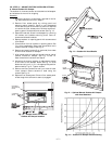
Fig. 11 — Field Control Wiring Raceway
and Compressor Location
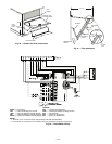
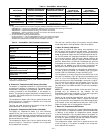
WIRE
CONNECTIONS
TO
LOW-VOLTAGE
SECTION
(CONNECTION
BOARD)
COOL STAGE 1
FAN
HEAT STAGE 1
COOL STAGE 2
HEAT STAGE 2
24 VAC HOT
24 VAC COM
N/A
OUTDOOR AIR
SENSOR
Y1/W2
G
W/W1
Y/Y2
O/W2
R
C
S1
S2
THERMOSTAT DIPSWITCH SETTINGS
R
G
Y1
Y2
W1
W2
C
IPD/X
ON
OFF
A
B
C
D
LEGEND
NOTE: Underlined letter indicates active thermostat output when
configured for A/C operation.
Fig. 10 — Low-Voltage Connections
Field Wiring


