—25—
M. Occupied/Unoccupied Switch
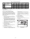
The EconoMi$er+ supports the use of a field-supplied occupied/
unoccupied switch. When the switch is closed it provides a
24-vac signal to the unit for occupied mode and when open,
there is no signal to indicate unoccupied mode. The control can
be configured to allow different minimum economizer damper
positions and to control how mechanical cooling will and will
not be used in the occupied mode.
NOTE: The remote potentiometer (see below) will override the
occupied minimum position if the potentiometer setting is
greater than the occupied minimum position.
For 3 to 12
1
/
2
ton units, a wire from J1-OCC (pin 4) and a
wire from J1-24V (pin 5) are wire-nutted together to jumper
the terminals.
An occupied/unoccupied switch can be field-installed in place
of the jumper to allow the user to force the control into occu-
pied or unoccupied mode of operation for EconoMi$er+
damper position. The occupied/unoccupied switch is required
if the user wants to use unoccupied free cooling or different
EconoMi$er+ damper vent positions in the unoccupied mode.
N. Power Exhaust
Refer to the Accessory Power Exhaust installation instructions
for information on installing the power exhaust accessory.
O. Remote EconoMi$er+ Enable Control
When the control is used with energy management systems that
enable and disable the EconoMi$er+, the user can install a field-
supplied enable/disable switch. The switch must be wired in
series with a 3K ohm, 1 watt or greater resistor. The switch is
wired to terminals ORH (pin 11) and VREF (pin 12) on J3. Refer
to the Start-Up section for details on how to configure the control.
P. R emote Potentiometer Occupied Minimum Position
The occupied minimum position set point remote potentiom-
eter (field-supplied) is used when requiring additional tem-
porary ventilation. The remote potentiometer (10K ohm -
closed damper, 100K ohm - open damper) will only control
the occupied minimum position.
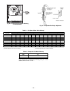
The accessory 5-in wiring plug, CRE+PLUG001A00 is
required to connect the potentiometer.
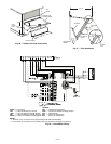
The plug is installed on pins 15, 16 and 17 on J3 of the
EconoMi$er+ controller. The pins are labeled with the ground
symbol, MIN and VREF on the EconoMi$er+ controller. See
Fig. 22. The pink wire from the harness is connected to pin
15 (ground symbol). The gray wire from the harness is con-
nected to pin 16 (MIN). The yellow wire from the harness is
connected to pin 16 (VREF). The wiring harness should be
extended with wires and wire nuts and routed from the
EconoMi$er+ controller to the remote potentiometer location.
NOTE: Pins 13 (ground symbol) and 14 (IAQ), which are
wired to the accessory 5-pin plug, are not used for the remote
potentiometer installation. They are used for an accessory
IAQ sensor (if required).
20
18
16
14
12
10
8
6
4
0102030
40
50
60 70
80
90
100
RH (%)
CURRENT
(mA)
10
20
30
40
50
60
70
80
90
5.6
7.2
8.8
10.4
12.0
13.6
15.2
16.8
18.4
HUMIDITY IN % RH
CURRENT IN mA
RH — Relative Humidity
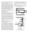
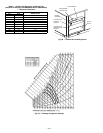
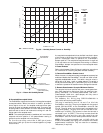
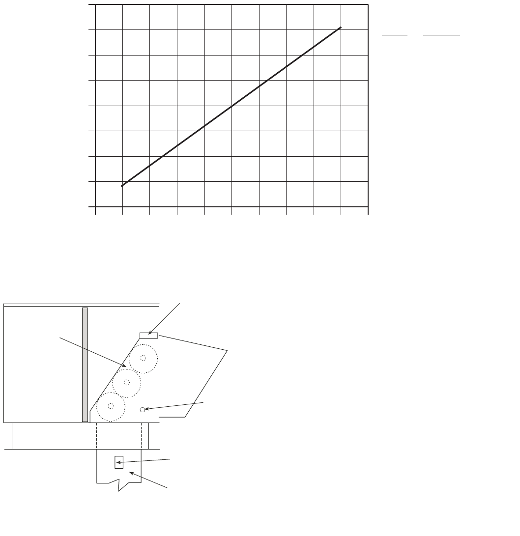
Fig. 30 — Humidity Sensor Current vs. Humidity
ECONOMI$ER+
ECONOMI$ER+
CONTROLLER
GROMMET
RETURN AIR
HUMIDITY SENSOR
RETURN DUCT
(FIELD-PROVIDED)
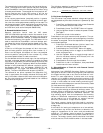
Fig. 31 — Return Air Humidity Sensor


