—44—
G. EconoMi$erIV Troubleshooting Completion
This procedure is used to return the EconoMi$erIV to opera-
tion. No troubleshooting or testing is done by performing the
following procedure.
1. Disconnect power at TR and TR1.
2. Set enthalpy potentiometer to previous setting.
3. Set DCV maximum position potentiometer to previ-
ous setting.
4. Set minimum position, DCV set point, and exhaust
potentiometers to previous settings.
5. Remove 620-ohm resistor from terminals S
R
and +.
6. Remove 1.2 kilo-ohm checkout resistor from terminals
S
O
and +. If used, reconnect sensor from terminals S
O
and +.
7. Remove jumper from TR to N.
8. Remove jumper from TR to 1.
9. Remove 5.6 kilo-ohm resistor from T and T1. Recon-
nect wires at T and T1.
10. Remove jumper from P to P1. Reconnect device at P
and P1.
11. Apply power (24 vac) to terminals TR and TR1.
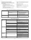
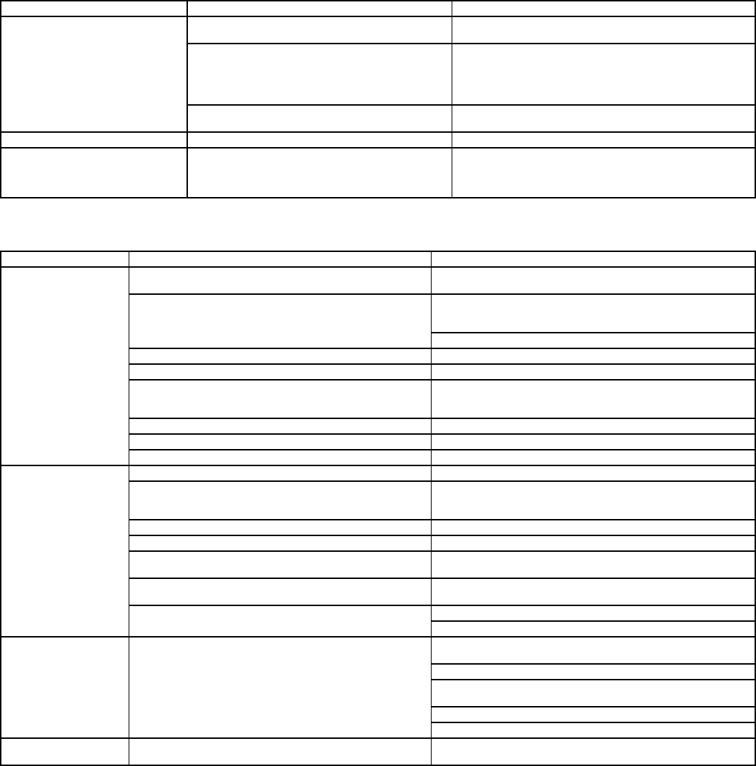
Table 26 — Perfect Humidity™ Dehumidification Subcooler Service Analysis
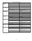
Table 27 — Heating Service Analysis
PROBLEM CAUSE REMEDY
Subcooler Will Not Energize No power to subcooler control transformer. Check power source. Ensure all wire connections
are tight.
No power from subcooler control transformer to liq-
uid line three-way valve.
1. Fuse open; check fuse. Ensure continuity of wiring.
2. Subcooler control low-pressure switch open.
Cycle unit off and allow low-pressure switch
to reset. Replace switch if it will not close.
3. Transformer bad; check transformer.
Liquid line three-way valve will not operate. 1. Solenoid coil defective; replace.
2. Solenoid valve stuck closed; replace.
Subcooler Will Not Deenergize Liquid Line three-way valve will not close. Valve is stuck open; replace.
Low System Capacity Low refrigerant charge or frosted coil. 1. Check charge amount. See system charging
section.
2. Evaporator coil frosted; check and replace
subcooler control low-pressure switch if necessary.
PROBLEM CAUSE REMEDY
Burners Will Not
Ignite.
Misaligned spark electrodes. Check flame ignition and sensor electrode positioning.
Adjust as needed.
No gas at main burners. Check gas line for air; purge as necessary. After purging
gas line of air, allow gas to dissipate for at least 5 minutes
before attempting to relight unit.
Check gas valve.
Water in gas line. Drain water and install drip leg to trap water.
No power to furnace. Check power supply, fuses, wiring, and circuit breaker.
No 24 v power supply to control circuit. Check transformer. Transformers with internal overcurrent
protection require a cool-down period before resetting.
Check 24-v circuit breaker; reset if necessary.
Miswired or loose connections. Check all wiring and wire nut connections.
Burned-out heat anticipator in thermostat. Replace thermostat.
Broken thermostat wires. Run continuity check. Replace wires if necessary.
Inadequate Heating. Dirty air filter. Clean or replace filter as necessary.
Gas input to unit too low. Check gas pressure at manifold. Clock gas meter for
input. If too low, increase manifold pressure or replace
with correct orifices.
Unit undersized for application. Replace with proper unit or add additional unit.
Restricted airflow. Clean filter, replace filter, or remove any restrictions.
Blower speed too low. Install alternate motor, if applicable, or adjust pulley to
increase fan speed.
Limit switch cycles main burners. Check rotation of blower, thermostat heat anticipator
settings, and temperature rise of unit. Adjust as needed.
Too much outdoor air. Adjust minimum position.
Check economizer operation.
Poor Flame
Characteristics.
Incomplete combustion (lack of combustion air)
results in:
Aldehyde odors, CO, sooting flame, or floating flame.
Check all screws around flue outlets and burner
compartment. Tighten as necessary.
Cracked heat exchanger.
Overfired unit — reduce input, change orifices, or adjust
gas line or manifold pressure.
Check vent for restriction. Clean as necessary.
Check orifice to burner alignment.
Burners Will Not Turn
Off.
Unit is locked into Heating mode for a one minute
minimum.
Wait until mandatory one minute time period has
elapsed or power to unit.


