


—26—
START-UP
Use the following information and Start-Up Checklist on
page CL-1 to check out unit PRIOR to start-up.
I. UNIT PREPARATION
Check that unit has been installed in accordance with these
installation instructions and all applicable codes.
II. COMPRESSOR MOUNTING
Compressors are internally spring mounted. Do not loosen or
remove compressor holddown bolts.
III. GAS PIPING
Check gas piping for leaks.
IV. REFRIGERANT SERVICE PORTS
Each refrigerant system has a total of 3 Schrader-type
service gage ports. One port is located on the suction line,
one on the compressor discharge line, and one on the liquid
line. In addition, Schrader-type valves are located under-
neath the low-pressure switches. Be sure that caps on the
ports are tight.
V. COMPRESSOR ROTATION
It is important to be certain the compressors are rotating in
the proper direction. To determine whether or not compres-
sors are rotating in the proper direction:
1. Connect service gages to suction and discharge pres-
sure fittings.
2. Energize the compressor.
3. The suction pressure should drop and the discharge
pressure should rise, as is normal on any start-up.
If the suction pressure does not drop and the discharge pres-
sure does not rise to normal levels:
1. Note that the evaporator fan is probably also rotating
in the wrong direction.
2. Turn off power to the unit.
3. Reverse any two of the incoming power leads.
4. Turn on power to the compressor.
The suction and discharge pressure levels should now move
to their normal start-up levels.
NOTE: When compressors are rotating in the wrong direc-
tion, the unit will have increased noise levels and will not
provide heating and cooling.
After a few minutes of reverse operation, the scroll compres-
sor internal overload protection will open, which will
activate the unit’s lockout and requires a manual reset.
Reset is accomplished by turning the thermostat on and off.
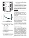
VI. INTERNAL WIRING
Check all electrical connections in unit control boxes; tighten
as required.
VII. CRANKCASE HEATER
Crankcase heater(s) is energized as long as there is power to
the unit and the compressor is not operating.
IMPORTANT: Unit power must be on for 24 hours prior to
start-up. Otherwise, damage to compressor may result.
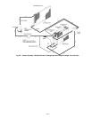
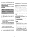
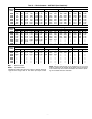
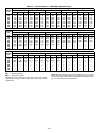
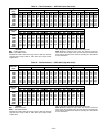
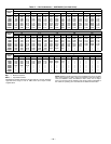
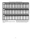
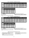
VIII. EVAPORATOR FAN
Fan belt and variable pulleys are factory-installed. See
Tables 13-20 for fan performance data. Be sure that fans
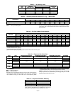
rotate in the proper direction. See Table 21 for air quantity
limits. See Table 22 for static pressure information for acces-
sories and options. See Table 23 for fan rpm at various motor
pulley settings. See Tables 24 and 25 for evaporator fan
motor data. To alter fan performance, see Evaporator Fan
Performance Adjustment section on page 35.
NOTE: A 3
1
/
2
-in. bolt and threaded plate are included in the
installer’s packet. They can be added to the motor support
channel below the motor mounting plate to aid in raising the
fan motor.
IX. CONDENSER-FANS AND MOTORS
Condenser fans and motors are factory set. Refer to
Condenser-Fan Adjustment section on page 36 as required.
Be sure that fans rotate in the proper direction.
X. RETURN-AIR FILTERS
Check that correct filters are installed in filter tracks (see
Table 1). Do not operate unit without return-air filters.
XI. OUTDOOR-AIR INLET SCREENS
Outdoor-air inlet screens must be in place before operating
unit.
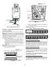
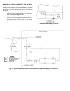
XII. GAS HEAT
Verify gas pressures before turning on heat as follows:
1. Turn off manual gas stop.
2. Connect pressure gage to supply gas pressure tap
(see Fig. 14).
3. Connect pressure gage to manifold pressure tap on
gas valve.
4. Turn on manual gas stop and set thermostat to
HEAT position. After the unit has run for several
minutes, verify that incoming pressure is 5.5 in. wg
or greater, and that the manifold pressure is
3.3 in. wg. If manifold pressure must be adjusted,
refer to Gas Valve Adjustment section on page 37.
5. After unit has been in operation for 5 minutes, check
temperature rise across the heat exchangers. See unit
informative plate for correct rise limits of the heat
supplied. Air quantities may need to be adjusted to
bring the actual rise to within the allowable limits.
WARNING: Disconnect gas piping from unit when
leak testing at pressure greater than
1
/
2
psig. Pres-
sures greater than
1
/
2
psig will cause gas valve damage
resulting in hazardous condition. If gas valve is sub-
jected to pressure greater than
1
/
2
psig, it must be
replaced before use. When pressure testing field-
supplied gas piping at pressures of
1
/
2
psig or less, a
unit connected to such piping must be isolated by man-
ually closing the gas valve.