—18—
XIII. STEP 13 — ADJUST FACTORY-INSTALLED OPTIONS
A. Optional EconoMi$erIV
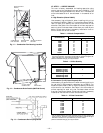
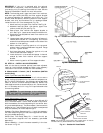
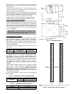
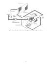
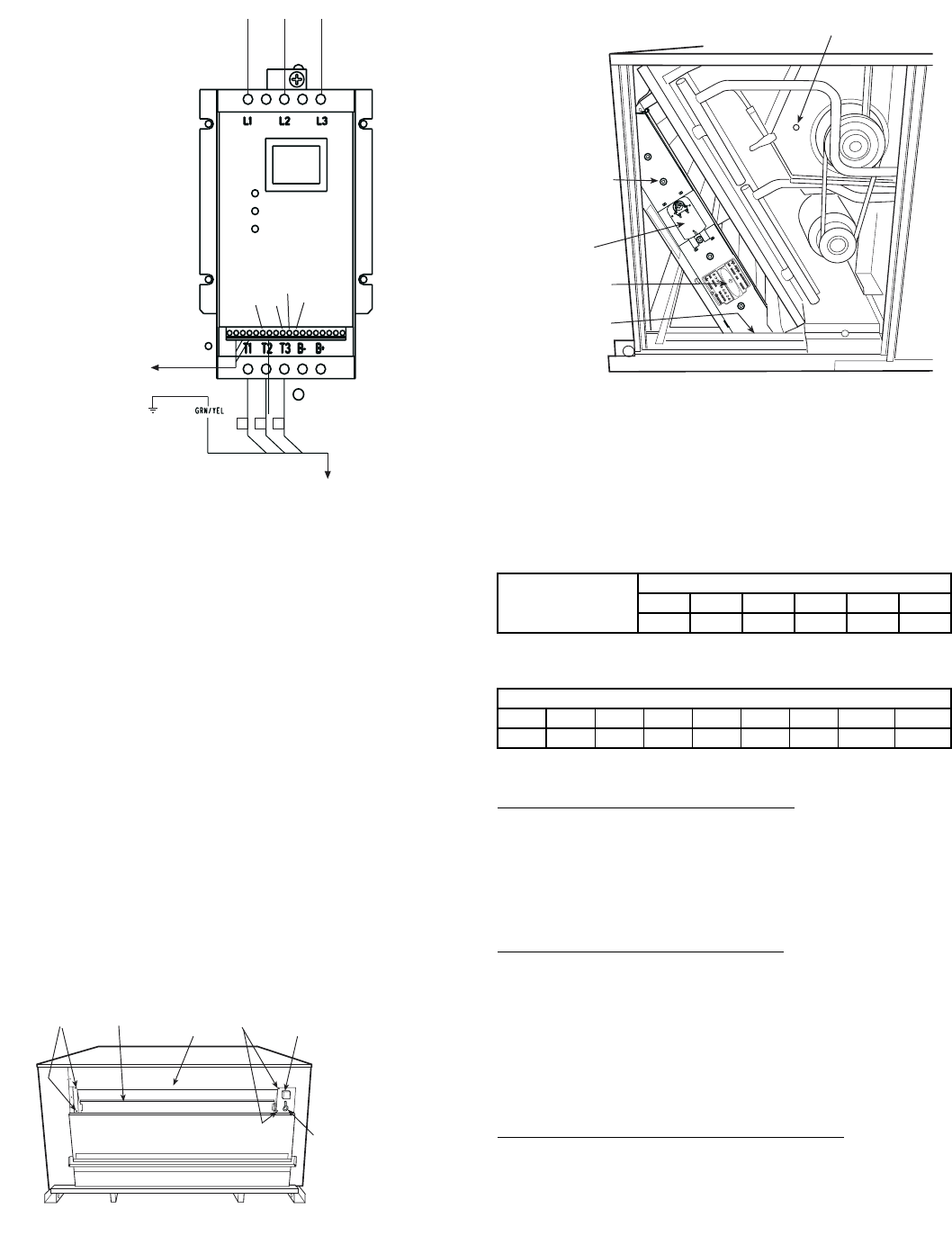
See Fig. 25 and 26 for EconoMi$erIV component locations.
NOTE: These instructions are for installing the optional
EconoMi$erIV only. Refer to the accessory EconoMi$erIV or
EconoMi$er2 installation instructions when field installing an
EconoMi$erIV or EconoMi$er2 accessory.
To complete installation of the optional EconoMi$erIV, per-
form the following procedure.
1. Remove the EconoMi$erIV hood. Refer to Step 11 —
Install Outdoor-Air Hood on page 15 for information
on removing and installing the outdoor-air hood.
2. Relocate outdoor air temperature sensor from ship-
ping position to operation position on EconoMi$erIV.
See Fig. 25.
IMPORTANT: Failure to relocate the sensor will result in the
EconoMi$erIV not operating properly.
3. Re-install economizer hood.
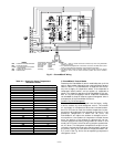
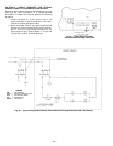
4. Install all EconoMi$erIV accessories. EconoMi$erIV
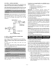
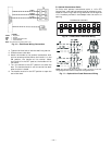
wiring is shown in Fig. 27.
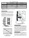
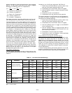
Outdoor air leakage is shown in Table 8. Return air pressure
drop is shown in Table 9.
Table 8 — Outdoor Air Damper Leakage
Table 9 — Return Air Pressure Drop (in. wg)
B. EconoMi$erIV Standard Sensors
Outdoor Air Temperature (OAT) Sensor
The outdoor air temperature sensor (HH57AC074) is a 10 to
20 mA device used to measure the outdoor-air temperature.
The outdoor-air temperature is used to determine when the
EconoMi$erIV can be used for free cooling. The sensor must
be field-relocated. See Fig. 25. The operating range of tem-
perature measurement is 40 to 100 F.
Supply Air Temperature (SAT) Sensor
The supply air temperature sensor is a 3 K thermistor
located at the inlet of the indoor fan. See Fig. 26. This sensor
is factory installed. The operating range of temperature
measurement is 0° to 158 F. See Table 10 for sensor tempera-
ture/resistance values.
The temperature sensor looks like an eyelet terminal with
wires running to it. The sensor is located in the “crimp end”
and is sealed from moisture.
Low Temperature Compressor Lockout Switch
The EconoMi$erIV is equipped with an ambient tempera-
ture lockout switch located in the outdoor air stream which
is used to lockout the compressors below a 42 F ambient tem-
perature. See Fig. 25.
DAMPER STATIC PRESSURE (in. wg)
0.2 0.4 0.6 0.8 1.0 1.2
LEAKAGE (cfm) 35 53 65 75 90 102
CFM
4500 5000 5400 6000 7200 7500 9000 10,000 11,250
0.040 0.050 0.060 0.070 0.090 0.100 0.110 0.120 0.140
256
2
12 13A
13B
13C
1
2
3
TO MOTOR(S)
TO PRESSURE
TRANSDUCER
BLK
YEL
BLU
FROM FUSE BLOCK
B
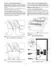
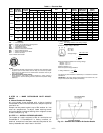
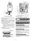
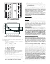
Fig. 24 — Motormaster® V Control
Fig. 25 — EconoMi$erIV Component Locations —
End View
ECONOMI$ERIV
OUTDOOR AIR
TEMPERATURE SENSOR
(INSTALLED OPERATION
POSITION)
SCREWS
SCREWS
FRAME
TOP
LOW TEMPERATURE
COMPRESSOR
LOCKOUT SWITCH
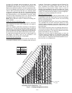
Fig. 26 — EconoMi$erIV Assembled in Unit —
Side View
ACTUATOR
ECONOMI$ERIV
FLANGE
AND SCREWS
(HIDDEN)
CONTROLLER
SUPPLY AIR
TEMPERATURE SENSOR
LOCATION
TR
1
2
4
V
a
c
C
O
M
T
R
2
4
V
a
c
H
O
T
1
2
3
4
5
EF
EF
1
+
_
P1
T
1
P
T
N
E
X
H
2
V
1
0
V
E
X
H
S
e
t
S
e
t
2
V
1
0
V
2
V
1
0
V
D
C
V
D
C
V
F
r
e
e
C
o
o
l
B
C
A
D
S
O
+
S
R
+
S
R
S
O
A
Q
1
A
Q
D
C
V
M
i
n
P
o
s
O
p
e
n
M
a
x
N
1


