


—20—
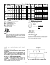
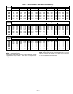
Table 11 — EconoMi$erIV Sensor Usage
*CRENTDIF004A00 and CRTEMPSN002A00 accessories are used on many different base units. As such, these kits may contain parts that will not be needed for
installation.
†CGCDXSEN004A00 is an accessory CO
2
sensor.
**CGCDXASP001A00 is an accessory aspirator box required for duct-mounted applications.
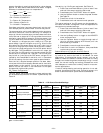
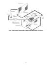
Differential Dry Bulb Control
For differential dry bulb control the standard outdoor dry
bulb sensor is used in conjunction with an additional acces-
sory return air sensor (part number CRTEMPSN002A00).
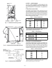
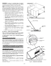
The accessory sensor must be mounted in the return
airstream. See Fig. 30.
In this mode of operation, the outdoor-air temperature is
compared to the return-air temperature and the lower tem-
perature airstream is used for cooling. When using this mode
of changeover control, turn the free cooling/enthalpy set point
potentiometer fully clockwise to the D setting. See Fig. 28.
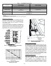
Outdoor Enthalpy Changeover
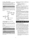
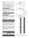
For enthalpy control, accessory enthalpy sensor (part num-
ber HH57AC078) is required. Replace the standard outdoor
dry bulb temperature sensor with the accessory enthalpy
sensor in the same mounting location. See Fig. 25. When the
outdoor air enthalpy rises above the outdoor enthalpy
changeover set point, the outdoor-air damper moves to its
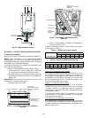
minimum position. The outdoor enthalpy changeover set
point is set with the outdoor enthalpy set point potentiome-
ter on the EconoMi$erIV controller. The set points are A, B,
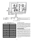
C, and D. See Fig. 31. The factory-installed 620-ohm jumper
must be in place across terminals SR and SR+ on the
EconoMi$erIV controller. See Fig. 25 and 32.
Differential Enthalpy Control
For differential enthalpy control, the EconoMi$erIV controller
uses two enthalpy sensors (HH57AC078 and
CRENTDIF004A00), one in the outside air and one in the
return airstream on the EconoMi$erIV frame. The
EconoMi$erIV controller compares the outdoor air enthalpy to
the return air enthalpy to determine EconoMi$erIV use. The
controller selects the lower enthalpy air (return or outdoor)
APPLICATION
ECONOMI$ERIV WITH OUTDOOR AIR
DRY BULB SENSOR
ECONOMI$ERIV WITH SINGLE
ENTHALPY SENSOR
Accessories Required Accessories Required
Outdoor Air Dry Bulb None. The outdoor air dry bulb sensor is factory installed. CRTEMPSN002A00*
Differential Dry Bulb CRTEMPSN002A00* (2) CRTEMPSN002A00*
Single Enthalpy HH57AC078 None. The single enthalpy sensor is factory installed.
Differential Enthalpy
HH57AC078
and
CRENTDIF004A00*
CRENTDIF004A00*
CO
2
for DCV Control using a
Wall-Mounted CO
2
Sensor
CGCDXSEN004A00
CO
2
for DCV Control using a
Duct-Mounted CO
2
Sensor
CGCDXSEN004A00†
and
CGCDXASP001A00**
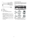
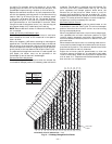
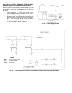
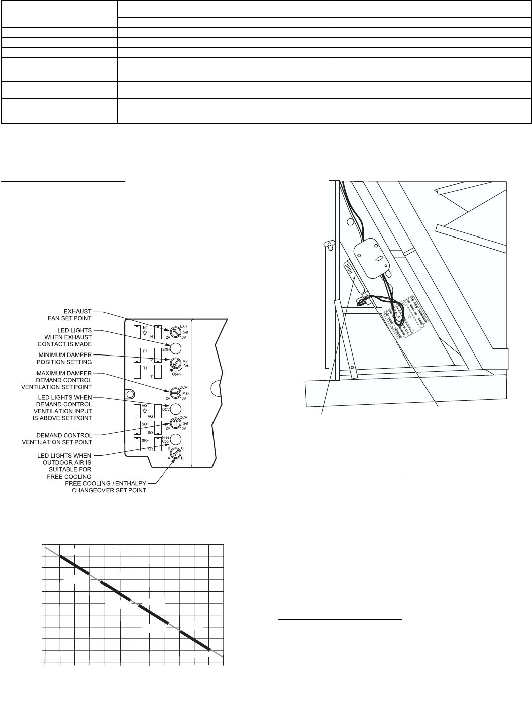
Fig. 28 — EconoMi$erIV Controller Potentiometer
and LED Locations
LED ON
LED ON
LED ON
LED ON
LED OFF
19
18
LED OFF
LED OFF
LED OFF
17
16
15
14
13
12
11
10
9
40
45
50
55
60
65
70
75
80
85
90
95
100
DEGREES FAHRENHEIT
mA
D
C
B
A
Fig. 29 — Outside Air Temperature
Changeover Set Points
IAQ
SENSOR
RETURN AIR
TEMPERATURE
OR ENTHALPY
SENSOR
T
R
1
2
4
V
ac
C
OM
T
R
2
4
Va
c
H
O
T
1
2
3
4
5
E
F
E
F
1
+
_
P
1
T
1
P
T
N
E
XH
2V 1
0
V
E
X
H
S
e
t
S
et
2
V
1
0
V
2V 1
0
V
D
C
V
D
C
V
F
r
e
e
C
o
o
l
B
C
A
D
S
O
+
S
R
+
S
R
S
O
A
Q1
A
Q
D
C
V
M
i
n
P
o
s
O
p
e
n
M
a
x
N
1
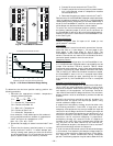
Fig. 30 — Return Air Temperature or Enthalpy
Sensor Mounting Location