—14—
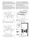
4. Tighten the Allen bolt to lock the shaft into position.
5. Close the control box door.
6. Attach the handle to the external access door with
the two screws provided. When the handle is in the
ON position, the handle will be vertical. When
the handle is in the OFF position, the handle will be
horizontal.
7. Turn the handle to the OFF position and close the
door. The handle should fit over the end of the shaft
when the door is closed.
8. The handle must be in the OFF position to open the
control box door.
D. Optional Convenience Outlet
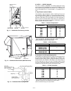
On units with optional convenience outlet, a 115-v GFI
(ground fault interrupt) convenience outlet receptacle is pro-
vided for field wiring. Field wiring should be run through the
7
/
8
-in. knockout provided in the basepan near the return air
opening.
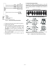
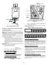
LEGEND
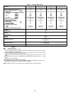
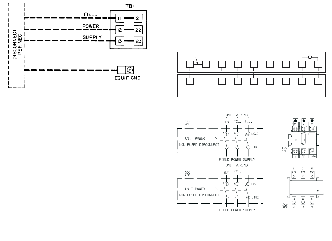
NOTE: The maximum wire size for TB1 is 2/0.
Fig. 15 — Field Power Wiring Connections
EQUIP — Equipment
GND — Ground
NEC — National Electrical Code
TB — Terminal Board
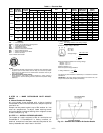
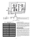
RH
RC
Y1 Y2
W1
W2
GC
X
L
X
C
G
W2
W1Y2
Y1
R
REMOVABLE JUMPER
RED
BLU
PNK
ORN
VIO
BLK
BRN
WHT
THERMOSTAT ASSEMBLY
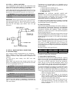
Fig. 16 — Field Control Thermostat Wiring
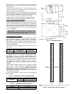
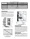
5L3 3L2 1L1 LINE
6T3 4T2 2T1 LOAD
NOTE: The disconnect takes the place of TB-1 as shown on the unit
wiring diagram label and the component arrangement label.
Fig. 17 — Optional Non-Fused Disconnect Wiring


