


12
CONTROLS (cont)
Heating, Units Without Economizer —
Upon a call for heating
through terminal W1, indoor (evaporator) fan contactor (IFC)
and heater contactor no. 1 (HC1) are energized. On units
equipped for 2 stages of heat, when additional heat is needed,
HC2 is energized through W2.
Heating, Units With Economizer —
When the room thermo-
stat calls for heat through terminal W1, the indoor (evaporator)
fan contactor (IFC) and heater contactor no. 1 (HC1) are ener-
gized. On units equipped for 2 stages of heat, when additional
heat is needed, HC2 is energized through W2. The economizer
damper moves to the minimum position. When the thermostat is
satisfied, the damper moves to the fully closed position.
SEQUENCE OF OPERATION SIZES 155-300
Cooling, Units Without EconoMi$er —
When thermostat calls
for cooling, terminals G and Y1 are energized. The indoor
(evaporator) fan contactor (IFC) and compressor contactor no. 1
(C1) are energized and evaporator-fan motor, compressor no. 1,
and condenser fans start. The condenser-fan motors run con-
tinuously while unit is cooling. If the thermostat calls for a sec-
ond stage of cooling by energizing Y2, compressor contactor
no. 2 (C2) is energized and compressor no. 2 starts.
Heating, Units Without EconoMi$er (If Accessory Heater is
Installed) —
Upon a call for heating through terminal W1, IFC
and heater contactor no. 1 (HC1) are energized. On units
equipped for 2 stages of heat, when additional heat is needed,
HC2 is energized through W2.
Cooling, Units With EconoMi$er —
When the OAT is above
the ECON SP set point and the room thermostat calls for
Stage 1 cooling (R to G + Y1), the indoor-fan motors (IFM) are
energized and the EconoMi$er damper modulates to minimum
position. The compressor contactor and OFC are energized to
start the compressor and outdoor-fan motor (OFM). After the
thermostat is satisfied, the damper modulates to the fully closed
position when the IFM is deenergized.
When the OAT is below the ECON SP setting and the room
thermostat calls for Stage 1 cooling (R to G + Y1), the
EconoMi$er modulates to the minimum position when the IFM
is energized. The EconoMi$er provides Stage 1 of cooling by
modulating the return and outdoor-air dampers to maintain a
55 F supply-air set point. If the supply-air temperature (SAT) is
greater than 57 F, the EconoMi$er modulates open, allowing a
greater amount of outdoor air to enter the unit. If the SAT drops
below 53 F, the outdoor-air damper modulates closed to reduce
the amount of outdoor air. When the SAT is between 53 and
57 F, the EconoMi$er maintains its position.
If outdoor air alone cannot satisfy the cooling requirements of
the conditioned space, and the OAT is above the MECH CLG
LOCKOUT set point, the EconoMi$er integrates free cooling
with mechanical cooling. This is accomplished by the strategies
below.
NOTE:
Compressors have a two-minute Minimum On and Mini-
mum Off.
1. If Y1 is energized, and the room thermostat calls for Y2
(2-stage thermostat), the compressor and OFC are ener-
gized. The position of the EconoMi$er damper is main-
tained at its current value.
2. If Y1 is energized for more than 20 minutes, and Y2 is not
energized (whether or not a 2-stage thermostat is used),
the compressor and OFC are energized. The position of the
EconoMi$er damper is maintained at its current value.
3. If Y1 is energized, and compressor no. 1 is already ener-
gized (see Step 2) and the room thermostat calls for Y2,
compressor no. 1 continues to operate. If Y2 remains
energized for more than 20 minutes, compressor no. 2 is
energized.
NOTE:
Compressor no. 2 cannot be energized unless there is a
signal for Y2 from the space thermostat.
4. If compressor no. 2 is energized, and the Y2 signal from the
thermostat is satisfied, compressors 1 and 2 are deener-
gized. Re-asserting Y2 will start compressor no. 1 and
(after a 20-minute interstage delay) compressor no. 2.
5. If compressor no. 1 is energized and the thermostat is satis-
fied, compressor no. 1, the OFM, and IFM are deenergized
and the EconoMi$er modulates closed.
When the OAT is below the MECH CLG LOCKOUT set point,
the compressors remain off.
Freeze Protection Thermostat(s) —
A freeze protection ther-
mostat (FPT) is located on the top and bottom of the evaporator
coil. It detects frost build-up and turns off the compressor, allow-
ing the coil to clear. Once frost has melted, the compressor can
be reenergized by resetting the compressor lockout.
Heating, Units With EconoMi$er (If Accessory Heater is
Installed) —
When the room thermostat calls for heat, the heat-
ing controls are energized as described in the Heating, Units
Without EconoMi$er section. The IFM is energized and the
EconoMi$er damper modulates to the minimum position. When
the thermostat is satisfied, the damper modulates closed.
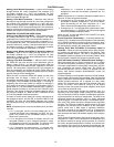
Units With Perfect Humidity™ Dehumidification Package —
When thermostat calls for cooling, terminals G and Y1 and/or
Y2 and the compressor contactor C1 and/or C2 are energized.
The indoor (evaporator) fan motor (IFM), compressors, and out-
door (condenser) fan motors (OFM) start. The OFMs run
continuously while the unit is in cooling. As shipped from the
factory, both Perfect Humidity dehumidification circuits are
always energized.
If Perfect Humidity circuit modulation is desired, a field-installed,
wall-mounted light-commercial thermidistat (with field-supplied
relay) is required. If the thermidistat is installed and calls for the
Perfect Humidity subcooler coil to operate, the relay switch
closes. This energizes the 3-way liquid line solenoid valve coils
(LLSV1 for circuit 1 and LLSV2 for circuit 2) of the Perfect
Humidity circuits, forcing the warm liquid refrigerant of the liquid
line to enter the subcooler coils.
As the warm liquid passes through the subcooler coils, it is
exposed to the cold supply airflow coming off the evaporator
coils and the liquid is further cooled to a temperature approach-
ing the evaporator coil leaving-air temperature. The state of the
refrigerant leaving the subcooler coils is a highly subcooled
liquid refrigerant. The liquid then enters a thermostatic expan-
sion valve (TXV) where the liquid is dropped to the evaporator
pressure. The TXVs can throttle the pressure drop of the liquid
refrigerant and maintain proper conditions at the compressor
suction valves over a wide range of operating conditions.
The liquid proceeds to the evaporator coils at a temperature
lower than normal cooling operation. This lower temperature is
what increases the latent and sensible capacity of the evapora-
tor coils.
The 2-phase refrigerant passes through the evaporators and is
changed into a vapor. The air passing over the evaporator coils
will become colder than during normal operation as a result of
the colder refrigerant temperatures. However, as it passes over
the subcooler coils, the air will be warmed, decreasing the sen-
sible capacity and reducing the sensible heat of the rooftop unit.