


9
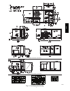
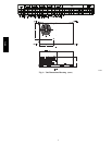
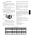
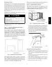
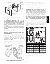
PositioningonCurb—
Position unit on roof curb so that the following clearances
are maintained:
1
/
4
in. (6.4 mm) clearance between the
roof curb and the base rail inside the front and rear, 0.0 in.
clearance between the roof curb and the base rail inside on
the duct end of the unit. This will result in the distance
between the roof curb and the base rail inside on the
condenser end of the unit being approximately equal to
Fig. 3, section C--C.
Although unit is weatherproof, guard against water from
higher level runoff and overhangs.
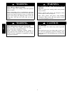
UNIT DAMAGE HAZARD
Failure to follow this caution may result in
equipment damage.
All panels must be in place when rigging. Unit is not
designed for handling by fork truck.
CAUTION
!
After unit is in position, remove rigging skids and
shipping materials.
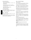
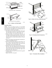
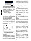
Step 7 — Convert to Horizontal and Connect
Ductwork (when required)
Unit is shipped in the vertical duct configuration. Unit
without factory--installed economizer or return air smoke
detector option may be field--converted to horizontal ducted
configuration. To convert to horizontal configuration,
remove screws from side duct opening covers and remove
covers. Using the same screws, install covers on vertical
duct openings with the insulation--side down. Seals around
duct openings must be tight. See Fig. 6.
C06108
Fig. 6 -- Horizontal Conversion Panels
Field--supplied flanges should be attached to horizontal
duct openings and all ductwork should be secured to the
flanges. Insulate and weatherproof all external ductwork,
joints, and roof or building openings with counter flashing
and mastic in accordance with applicable codes.
Do not cover or obscure visibility to the unit’s informative
data plate when insulating horizontal ductwork.
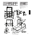
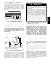
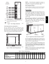
Step 8 — Install Outside Air Hood
The outdoor hood components are shipped in a box
located in the unit return air compartment behind the
outdoor--ar opening access panel (or economizer). Access
is through the filter access panel. See Fig. 7.
FILTERACCESS PANEL
OUTDOOR-AIR OPENINGAND
INDOOR COILACCESS PANEL
COMPRESSOR
ACCESS PANEL
C06023
Fig. 7 -- Typical Access Panel Locations
1. To remove the existing unit filter access panel, raise
the panel and swing the bottom outward. The panel is
now disengaged from the track and can be removed.
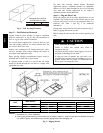
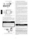
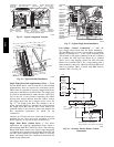
2. To remove the component box from its shipping posi-
tion, remove the screw holding the hood box bracket
to the top of the economizer. Slide the hood box out
of the unit. See Fig. 8.
H
o
o
d
B
o
x
HOOD BOX
BRACKET
C06024
Fig. 8 -- Hood Box Removal
Motorized 2--Position Damper Hood —
1. Assemble outdoor--air hood top and side plates as
shown in Fig. 9. Install seal strips on hood top and
sides. Put aside screen retainer and screws for later
assembly.
2. Fasten hood top and side plate assembly to unit with
screws provided. See Fig. 9.
3. Slide outdoor--air inlet screen into screen track on
hood side plates. While holding screen) in place,
fasten screen retainer to hood using screws provided.
4. Replace filter access panel. See Fig. 7.
551J
j