


15
X
C
G
W2
C
W2
G
W1
O/B/Y2
Y2
R
W1
R
Y1
Y1
T
H
E
R
M
O
S
T
A
T
(Note 1) (Note 2)
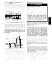
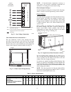
Note 1: Typical multi-function marking. Follow manufacturer’s configuration
Instructions to select Y2.
Note 2: Y2 to Y2 connection required on single-stage cooling units when
integrated economizer function is desired.
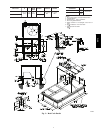
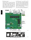
Field Wiring
Central
Terminal
Board
Typical
Thermostat
Connections
C08069
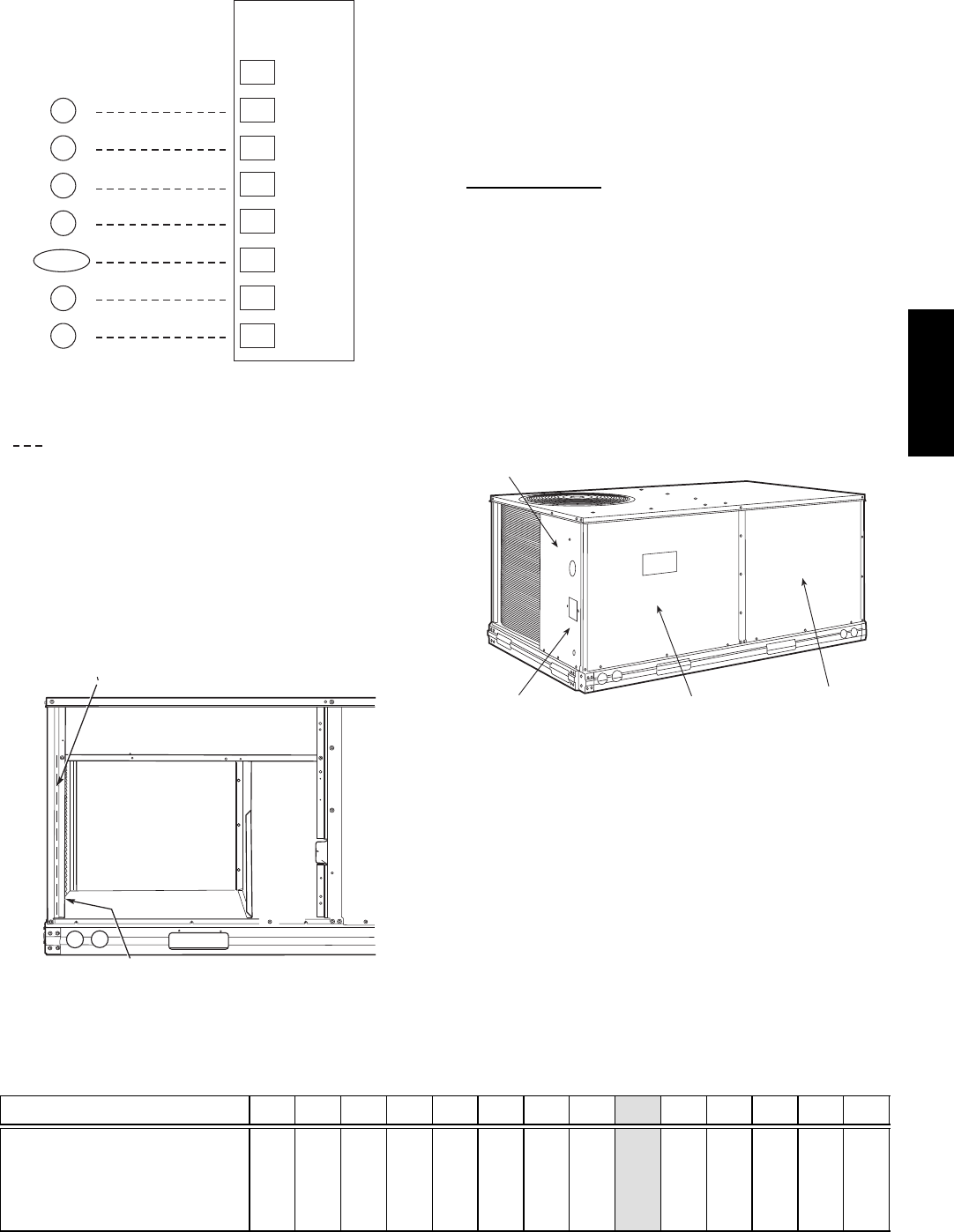
Fig. 22 -- Low--Voltage Connections
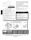
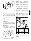
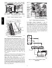
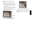
Unit without thru--base connection kit —
Pass the thermostat control wires through the hole
provided in the corner post; then feed the wires through
the raceway built into the corner post to the control box.
Pull the wires over to the terminal strip on the upper--left
corner of the Controls Connection Board. See Fig. 23.
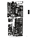
RACEWAY
HOLE IN END PANEL (HIDDEN)
C08027
Fig. 23 -- Field Control Wiring Raceway
NOTE: If thru--the--bottom connections accessory is
used, refer to the accessory installation instructions for
information on routing power and control wiring.
Heat Anticipator Settings —
Set heat anticipator settings at 0.14 amp for the first stage
and 0.14 amp for second--stage heating, when available.
Electric Heaters
551J units may be equipped with field--installed accessory
electric heaters. The heaters are modular in design, with
heater frames holding open coil resistance wires strung
through ceramic insulators, line--break limit switches and
a control contactor. One or two heater modules may be
used in a unit.
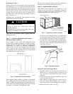
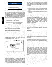
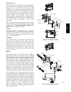
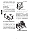
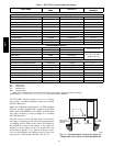
Heater modules are installed in the compartment below
the indoor (supply) fan outlet. Access is through the
indoor access panel. Heater modules slide into the
compartment on tracks along the bottom of the heater
opening. See Fig. 24, Fig. 25 and Fig. 26.
DISCONNECT MOUNTING
LOCATION
UNIT BLOCK-OFF
PANEL
OUTDOOR
ACCESS PANEL
INDOOR
ACCESS
PANEL
C08133
Fig. 24 -- Typical Access Panel Location (3--6 Ton)
Not all available heater modules may be used in every
unit. Use only those heater modules that are UL listed for
use in a specific size unit. Refer to the label on the unit
cabinet for the list of approved heaters.
Unit heaters are marked with Heater Model Numbers. But
heaters are ordered as and shipped in cartons marked with
a corresponding heater Sales Package part number. See
Table 2 for correlation between heater Model Number and
Sales Package part number.
NOTE: The value in position 9 of the part number differs
between the sales package part number (value is 1) and a
bare heater model number (value is 0).
Table 2 – Heater Model Number
Bare Heater Model Number C R H E A T E R 0 0 1 A 0 0
Heater Sales Package PNO
Includes:
Bare Heater
Carton and packing materials
Installation sheet
C R H E A T E R 1 0 1 A 0 0
551J
j