


14
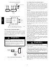
NOTICE
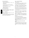
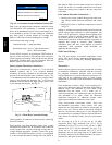
Convenience Outlet Utilization
Maximum Intermittent use : 15 Amps 2 to 3 Hours
Maximum Continuous use : 8 Amps 24/7
50HJ542739 3.0
A9225
Fig. 20 -- Convenience Outlet Utilization Notice Label
Duty Cycle: the unit--powered convenience outlet has a duty
cycle limitation. The transformer is intended to provide
power on an intermittent basis for service tools, lamps, etc; it
is not intended to provide 15--amps loading for continuous
duty loads (such as electric heaters for overnight use).
Observe a 50% limit on circuit loading above 8--amps.
Convenience outlet usage rating:
Continuous usage: 8 amps maximum
Intermittent usage: up to 15 amps maximum for
up to 2 hours maximum
Test the GFCI receptacle by pressing the TEST button on
the face of the receptacle to trip and open the receptacle.
Check for proper grounding wires and power line phasing
if the GFCI receptacle does not trip as required. Press the
RESET button to clear the tripped condition.
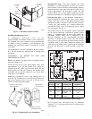
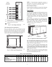
Factory--Option Thru--Base Connections —
This service connection kit consists of a
1
/
2
--in electrical
bulkhead connector and a
3
/
4
--in electrical bulkhead
connector, all factory--installed in the embossed (raised)
section of the unit basepan in the condenser section. The
3
/
4
--in bulkhead connector enables the low--voltage control
wires to pass through the basepan. The
1
/
2
--in electrical
bulkhead connector allows the high--voltage power wires
to pass through the basepan. See Fig. 21.
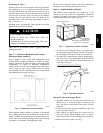
LOW VOLTAGE
CONDUIT
CONNECTOR
HIGH VOLTAGE
CONDUIT
CONNECTOR
C08637
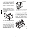
Fig. 21 -- Thru--Base Connection Fittings
Check tightness of connector lock nuts before connecting
electrical conduits.
Field--supplied and field--installed liquid tight conduit
connectors and conduit may be attached to the connectors
on the basepan. Pull correctly rated high voltage and low
voltage through appropriate conduits. Connect the power
conduit to the internal disconnect (if unit is so equipped)
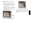
or to the external disconnect (through unit side panel). A
hole must be field cut in the main control box bottom on
the left side so the 24--v control connections can be made.
Connect the control power conduit to the unit control box
at this hole.
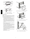
Units without Thru--Base Connections —
1. Install power wiring conduit through side panel open-
ings. Install conduit between disconnect and control
box.
2. Install power lines to terminal connections as shown
in Fig. 15.
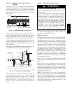
Voltage to compressor terminals during operation must be
within voltage range indicated on unit nameplate. See
Table 4. On 3--phase units, voltages between phases must
be balanced within 2% and the current within 10%. Use
the formula shown in the legend for Table 5, Note 2 to
determine the percent of voltage imbalance. Operation on
improper line voltage or excessive phase imbalance
constitutes abuse and may cause damage to electrical
components. Such operation would invalidate any
applicable Bryant warranty.
Field Control Wiring —
The 551J unit requires an external temperature control
device. This device can be a thermostat emulation device
provided as part of a third--party Building Management
System.
Thermostat —
Install a Bryant--approved accessory thermostat according
to installation instructions included with the accessory.
For complete economizer function, select a two--stage
cooling thermostat. Locate the thermostat accessory on a
solid wall in the conditioned space to sense average
temperature in accordance with the thermostat installation
instructions.
If the thermostat contains a logic circuit requiring 24--v
power, use a thermostat cable or equivalent single leads of
different colors with minimum of seven leads. If the
thermostat does not require a 24--v source (no “C”
connection required), use a thermostat cable or equivalent
with minimum of six leads. Check the thermostat
installation instructions for additional features which
might require additional conductors in the cable.
Using unit--mounted convenience outlets: Units with
unit--mounded convenience outlet circuits will often
require that two disconnects be opened to de--energize all
power to the unit. Treat all units as electrically energized
until the convenience outlet power is also checked and
de--energization is confirmed. Observe National Electrical
Code Article 210, Branch Circuits, for use of convenience
outlets.
For wire runs up to 50 ft. (15 m), use no. 18 AWG
(American Wire Gage) insulated wire [35_C(95_F)
minimum]. For 50 to 75 ft. (15 to 23 m), use no. 16 AWG
insulated wire [35_C(95_F) minimum]. For over 75 ft.
(23 m), use no. 14 AWG insulated wire [35_C(95_F)
minimum]. All wire sizes larger than no. 18 AWG cannot
be directly connected to the thermostat and will require a
junction box and splice at the thermostat.
551J
j