


5
INSTALLATION
Jobsite Survey
Complete the following checks before installation.
1. Consult local building codes and the NEC (National
Electrical Code) ANSI/NFPA 70 for special installa-
tion requirements.
2. Determine unit location (from project plans) or select
unit location.
3. Check for possible overhead obstructions which may
interfere with unit lifting or rigging.
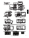
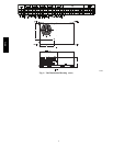
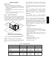
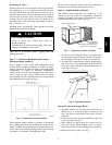
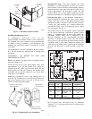
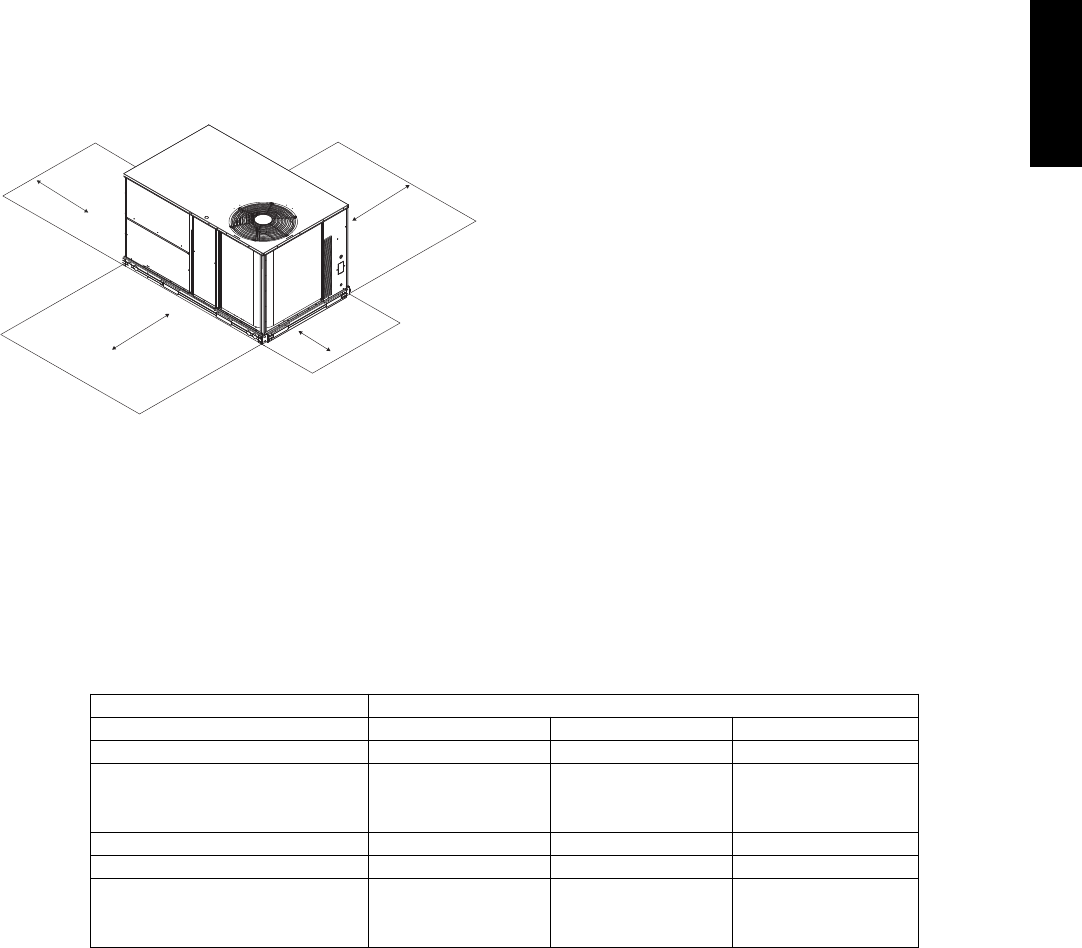
Step 1 — Plan for Unit Location
Select a location for the unit and its support system (curb
or other) that provides for minimum clearances required
for safety (including clearance to combustible surfaces),
unit performance and service access below, around and
above unit as specified in unit drawings. See Fig. 2.
18” (457)
42" (1067)
18" (457)
42" (1067)
1
Required bottom condensate drain connection.
Otherwise, 36” (914mm) for condensate connection.
1
C07459
Fig. 2 -- Service Clearance Dimensional Drawing
NOTE: Consider also the effect of adjacent units.
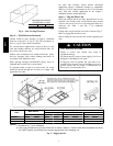
Unit may be installed directly on wood flooring or on
Class A, B, or C roof--covering material when roof curb is
used.
Do not install unit in an indoor location. Do not locate air
inlets near exhaust vents or other sources of contaminated
air.
Although unit is weatherproof, avoid locations that permit
water from higher level runoff and overhangs to fall onto
the unit.
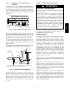
Select a unit mounting system that provides adequate
height to allow installation of condensate trap per
requirements.RefertoStep9—InstallExternal
Condensate Trap and Line – for required trap dimensions.
Roof mount —
Check building codes for weight distribution
requirements. Unit operating weight is shown in Table 1.
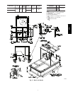
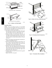
Step 2 — Plan for Sequence of Unit Installation
The support method used for this unit will dictate different
sequences for the steps of unit installation. For example,
on curb--mounted units, some accessories must be
installed on the unit before the unit is placed on the curb.
Review the following for recommended sequences for
installation steps.
Curb--mounted installation —
Install curb
Install field--fabricated ductwork inside curb
Install accessory thru--base service connection package
(affects curb and unit) (refer to accessory installation
instructions for details)
Prepare bottom condensate drain connection to suit
planned condensate line routing (refer to Step 9 for
details)
Rig and place unit
Install outdoor air hood
Install condensate line trap and piping
Make electrical connections
Install other accessories
Table 1 – Operating Weights
551J UNITS LB (KG)
Component *04 *05 *06
Base Unit 458 (208) 545 (247) 550 (249)
Economizer
Vertical 50 (23) 50 (23) 50 (23)
Horizontal 80 (36) 80 (36) 80 (36)
Cu Fins 25 (11) 43 (20) 56 (25)
Powered Outlet 32 (15) 32 (15) 32 (15)
Curb
14---in/356 mm 110 (50) 110 (50) 110 (50)
24---in/610 mm 145 (66) 145 (66) 145 (66)
551J
j