


8
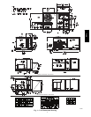
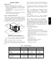
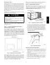
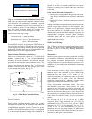
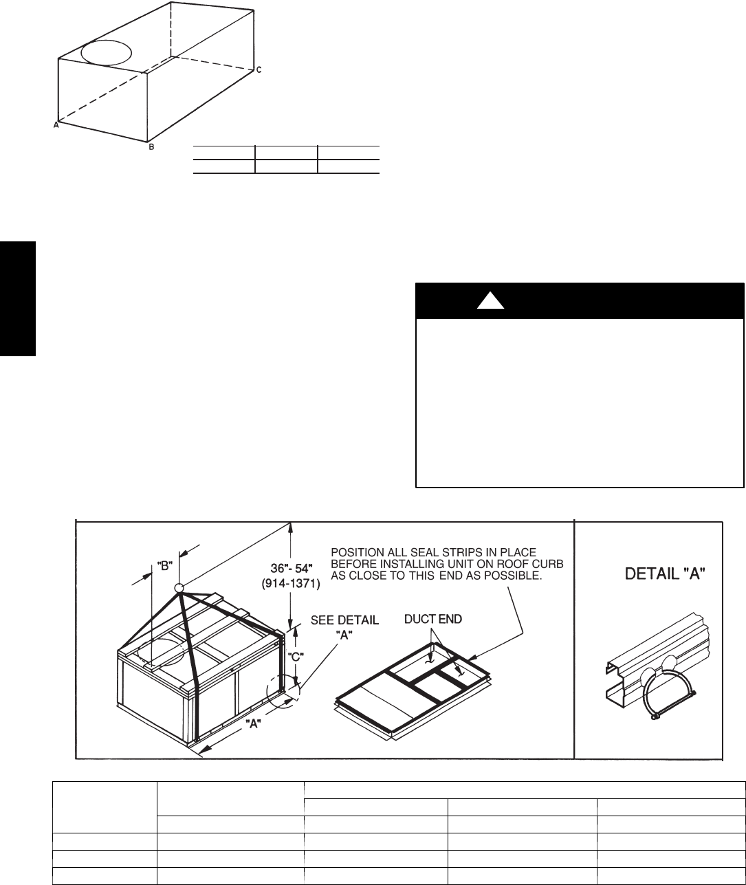
A-B
0.5” (13)
B-C
1.0” (25)
A-C
1.0” (25)
MAXIMUM ALLOWABLE
DIFFERENCE IN. (MM)
C06110
Fig. 4 -- Unit Leveling Tolerances
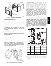
Step 5 — Field Fabricate Ductwork
Cabinet return-air static pressure (a negative condition)
shall not exceed 0.35 in. wg (87 Pa) with economizer or
0.45 in. wg (112 Pa) without economizer.
For vertical ducted applications, secure all ducts to roof
curb and building structure on vertical ducted units. Do
not connect ductwork to unit.
Insulate and weatherproof all external ductwork, joints,
and roof openings with counter flashing and mastic in
accordance with applicable codes.
Ducts passing through unconditioned spaces must be
insulated and covered with a vapor barrier.
If a plenum return is used on a vertical unit, the return
should be ducted through the roof deck to comply with
applicable fire codes.
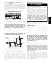
For units with accessory electric heaters: Horizontal
applications require a minimum clearance to combustible
surfaces of 1--in (25 mm) from duct for first 12--in (305 mm)
away from unit. Vertical applications do not require a
minimum clearance around ductwork.
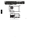
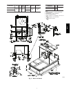
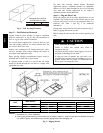
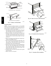
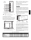
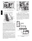
Step 6 — Rig and Place Unit
Keep unit upright and do not drop. Spreader bars are not
required if top crating is left on unit. Rollers may be used
to move unit across a roof. Level by using unit frame as a
reference. See Table 1 and Fig. 5 for additional
information.
Lifting holes are provided in base rails as shown in Fig. 5.
Refer to rigging instructions on unit.
Before setting the unit onto the curb, recheck gasketing on
curb.
UNIT DAMAGE HAZARD
Failure to follow this caution may result in
equipment damage.
All panels must be in place when rigging. Unit is not
designed for handling by fork truck.
If using top crate as spreader bar, once unit is set,
carefully lower wooden crate off building roof top to
ground. Ensure that no people or obstructions are
below prior to lowering the crate.
CAUTION
!
C06005
UNIT
MAX W EIGHT
DIMENSIONS
A B C
LB KG IN MM IN MM IN MM
551J*04A 700 318 74.5 1890 36.5 925 33.5 850
551J*05A 830 377 74.5 1890 36.5 925 41.5 1055
551J*06A 865 393 74.5 1890 36.0 915 41.5 1055
NOTES:
1. Dimensions in ( ) are in millimeters.
2. Hook rigging shackles through holes in base rail, as shown in detail “A.” Holes in base rails are c entered around the
unit center of gravity. Use wooden top to prevent rigging straps from damaging unit.
Fig. 5 -- Rigging Details
551J
j