


23
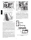
Outdoor Air Temperature (OAT) Sensor -- The OAT is
factory--mounted in the EconoMi$er2 (FIOP or
accessory). It is a nominal 10k ohm thermistor attached to
an eyelet mounting ring.
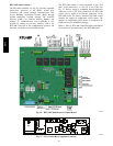
EconoMi$er2 -- The RTU--MP control is used with
EconoMi$er2 (option or accessory) for outdoor air
management. The damper position is controlled directly
by the RTU--MP control; EconoMi$er2 has no internal
logic device.
Outdoor air management functions can be enhanced with
field--installation of these accessory control devices:
Enthalpy control (outdoor air or differential sensors)
Space CO
2
sensor
Outdoor air CO
2
sensor
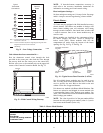
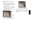
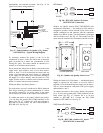
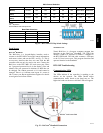
Field Connections -- Field connections for accessory
sensors and input devices are made the RTU--MP, at plugs
J1, J2, J4, J5, J11 and J20. All field control wiring that
connects to the RTU--MP must be routed through the
raceway built into the corner post as shown in Fig. 23.
The raceway provides the UL required clearance between
high-- and low--voltage wiring. Pass the control wires
through the hole provided in the corner post, then feed the
wires thorough the raceway to the RTU--MP. Connect to
the wires to the removable Phoenix connectors and then
reconnect the connectors to the board.
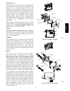
Space Temperature (SPT) Sensors
A field--supplied Byrant space temperature sensor is
required with the RTU--MP to monitor space temperature.
There are 3 sensors available for this application:
S 33ZCT55SPT, space temperature sensor with override
button
S 33ZCT56SPT, space temperature sensor with override
button and setpoint adjustment
S 33ZCT59SPT, space temperature sensor with LCD
(liquid crystal display) screen, override button, and
setpoint adjustment
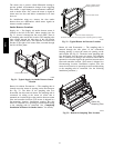
Use 20 gauge wire to connect the sensor to the controller.
The wire is suitable for distances of up to 500 ft. Use a
three--conductor shielded cable for the sensor and setpoint
adjustment connections. If the setpoint adjustment
(slidebar) is not required, then an unshielded, 18 or 20
gauge, two--conductor, twisted pair cable may be used.
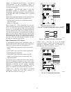
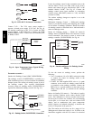
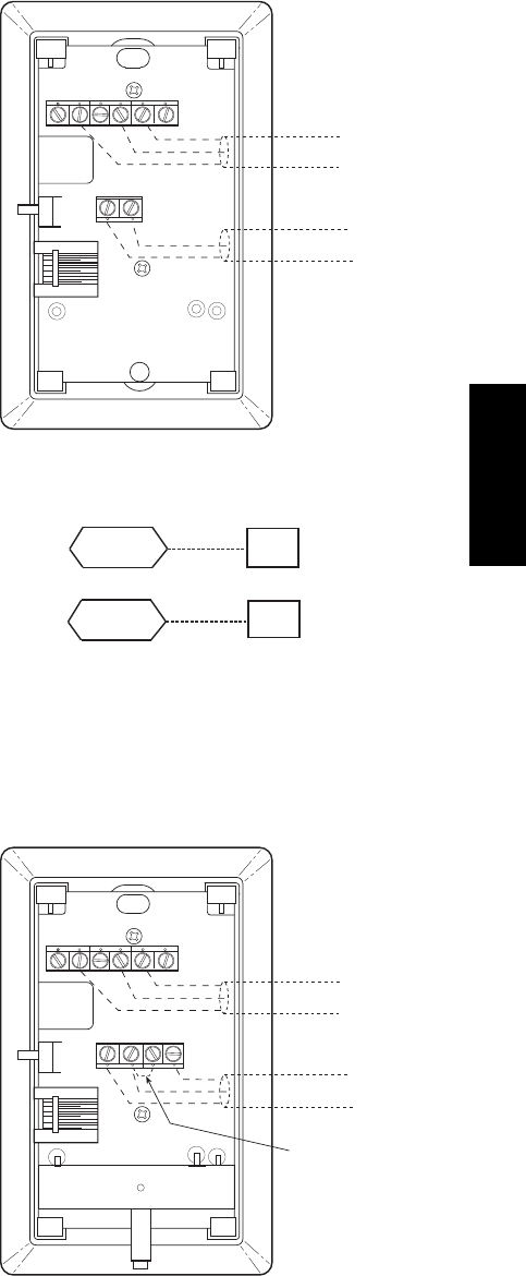
Connect T--55 -- See Fig. 40 for typical T--55 internal
connections. Connect the T--55 SEN terminals to
RTU--MP J20--1 and J20--2. See Fig. 41.
2
3
45
61
SW1
SEN
BRN (GND)
BLU (SPT)
RED(+)
WHT(GND)
BLK(-)
CCN COM
SENSOR WIRING
C08201
Fig. 40 -- T--55 Space Temperature Sensor Wiring
SEN
SEN
J20-1
J20-2
C08460
Fig. 41 -- RTU--MP T--55 Sensor Connections
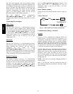
Connect T--56 -- See Fig. 42 for T--56 internal
connections. Install a jumper between SEN and SET
terminals as illustrated. Connect T--56 terminals to
RTU--MP J20--1, J20--2 and J20--3 per Fig. 43.
2
3
45
61
SW1
SEN
SET
Cool Warm
BRN (GND)
BLU (SPT)
RED(+)
WHT(GND)
BLK(-)
CCN COM
SENSOR WIRING
JUMPER
TERMINALS
AS SHOWN
BLK
(T56)
C08202
Fig. 42 -- T--56 Internal Connections
551J
j