


—
5
—
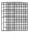
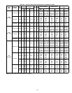
UNIT
548D
STD UNIT
WEIGHT
DURABLADE
ECONOMIZER
WEIGHT
ECONOMI$ER
WEIGHT
CORNER
WEIGHT
(A)
CORNER
WEIGHT
(B)
CORNER
WEIGHT
(C)
CORNER
WEIGHT
(D)
“H” “J” “K”
Lb Kg Lb Kg Lb Kg Lb Kg Lb Kg Lb Kg Lb Kg Ft-in. mm Ft-in. mm Ft-in. mm
090
940 426 44 20 62 28 207 94 178 81 254 115 301 136 2- 0
7
/
8
632 3-5
5
/
16
1050 2-9
11
/
16
856
102
965 438 44 20 62 28 212 96 183 83 261 119 309 140 2- 0
7
/
8
632 3-5
5
/
16
1050 2-9
11
/
16
856
120
1015 460 44 20 62 28 223 101 193 88 274 124 325 147 2-10
7
/
8
885 4-1
5
/
16
1253 3-0
3
/
8
924
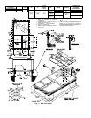
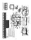
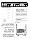
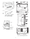
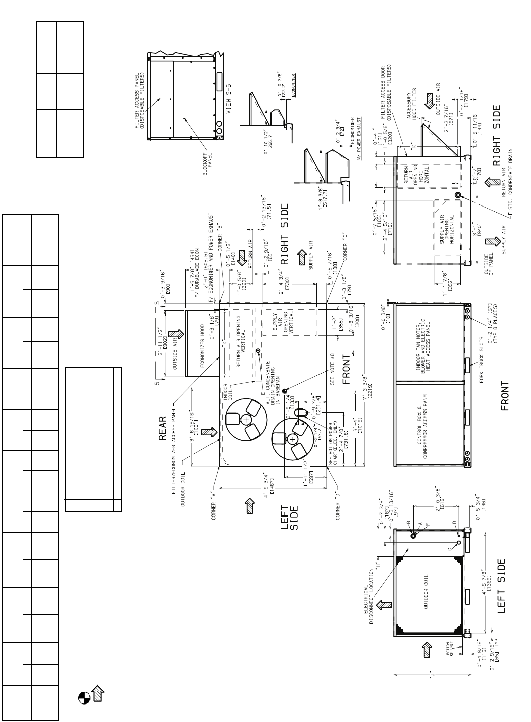
NOTES:
1. Dimensions in [ ] are in millimeters.
2. Center of gravity.
3. Direction of airflow.
4. Ductwork to be attached to accessory roof curb only.
5. Minimum clearance (local codes or jurisdiction may prevail):
a. Bottom to combustible surfaces (when not using curb) 0 inches,
on horizontal discharge units with electric heat 1 in. clearance to
ductwork for 1 ft.
b. Condenser coil, for proper airflow, 36 in. one side, 12 in. the
other. The side getting the greater clearance is optional.
c. Overhead, 60 in. to assure proper condenser fan operation.
d. Between units, control box side, 42 in. per NEC (National Electri-
cal Code).
e. Between unit and ungrounded surfaces, control box side, 36 in.
per NEC.
f. Between unit and block or concrete walls and other grounded
surfaces, control box side, 42 in. per NEC.
g. Horizontal supply and return end, 0 inches.
6. With the exception of the clearance for the condenser coil as stated
in Notes 5a, b, and c, a removable fence or barricade requires no
clearance.
7. Units may be installed on combustible floors made from wood or
Class A, B, or C roof covering material.
8. The vertical center of gravity is 1
′
-7
1
/
2
″
[495] for 090 and 102, 2
′
-0
″
[610] for 120 up from the bottom of the base rail.
CONNECTION SIZES
A
1
3
/
8
″
Dia. [35] Field Power Supply Hole
B
2
1
/
2
″
Dia. [64] Power Supply Knockout
C
1
3
/
4
″
Dia. [44] Charging Port Hole
D
7
/
8
″
Dia. [22] Field Control Wiring Hole
E
3
/
4
″
— 14 NPT Condensate Drain
F
2
″
Dia. [51] Power Supply Knockout
BOTTOM POWER CHART, THESE HOLES REQ’D
FOR USE WITH ACCESSORY PACKAGES —
CRBTMPWR001A00 (
1
/
2
″
,
3
/
4
″
) OR
CRBTMPWR002A00 (
1
/
2
″
, 1
1
/
4
″
)
*Select either
3
/
4
″
or 1
1
/
4
″
for power, depending on wire
size.
THREADED
CONDUIT
SIZE
WIRE
USE
REQ’D HOLE
SIZES
(Max.)
1
/
2
″
″″
″
24 V
7
/
8
″
[22.2]
3
/
4
″
″″
″
Power* 1
1
/
8
″
[28.4]
1
1
/
4
″
″″
″
FPT
Power* 1
3
/
4
″
[44.4]
Fig. 6 — Base Unit Dimensions