


—
15
—
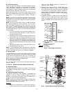
C. Optional EconoMi$er
See Fig. 22 for EconoMi$er component locations.
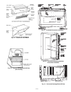
1. To remove the existing unit filter access panel, raise
the panel and swing the bottom outward. The panel is
now disengaged from the track and can be removed.
Remove the indoor coil access panel and discard. See
Fig. 23.
Controller should be mounted in vertical position as
shown in Fig. 22.
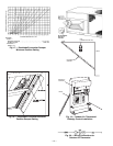
2. Assemble the hood assembly as follows:
Remove the EconoMi$er hood from its packaging.
Locate the outdoor air opening panel. See Fig. 24.
Remove hood assembly shipping brackets located on
back (sloped) side of EconoMi$er assembly. These
brackets are used to retain hood assembly during
shipping only.
3. Install the
1
/
8
x
3
/
4
in. seal strip on the exhaust air
hood side panels and the bottom bracket. Assemble
the exhaust air hood to the outdoor air opening panel
as shown in Fig. 24, using the screws provided. Do
not attach hood assembly to unit at this time.
4. Install the
1
/
8
x
7
/
8
in. seal strip on the outdoor air
hood top and side panels. Assemble the outdoor air
hood to the outdoor air opening panel as shown in
Fig. 25, using the screws provided. Do not attach hood
assembly to the unit as this time.
5. Slide the outdoor air inlet screens into the screen
track on the hood side panels. While holding the
screens in place, fasten the screen retainer to the
hood using the screws provided. Repeat the process
for the barometric exhaust air screen. Do not attach
completed (Fig. 26) hood assembly to unit at this time.
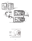
6. Install the return air block-off plate over the return
air duct opening. See Fig. 27.
7. Slide the EconoMi$er assembly into the rooftop unit.
See Fig. 28 and 29.
NOTE: Be sure to engage rear EconoMi$er flange under tabs
in return air opening of the unit base. See Fig. 28.
8. Install the outdoor air block-off plate, then secure the
EconoMi$er with the screws provided. See Fig. 27
and 29.
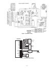
9. Remove and save the 12-pin blue and yellow wire
jumper plug from the unit wiring harness located in
the upper left corner and insert the EconoMi$er plug.
Refer to wiring diagram Fig. 30 and 31. Also refer to
Fig. 32 if installing an accessory power exhaust.
10. Remove shipping tape from barometric relief damp-
ers and ensure dampers move freely.
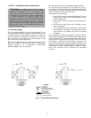
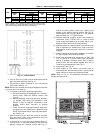
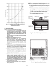
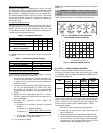
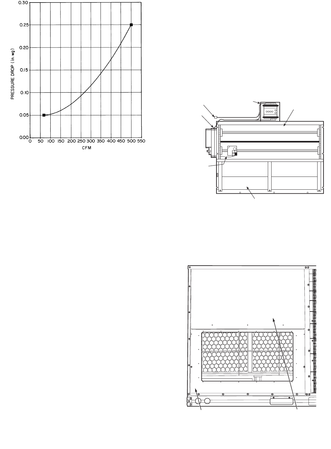
Fig. 21 — Durablade Economizer Barometric Relief
Damper Characteristics
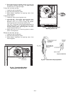
CONTROLLER
BAROMETRIC
RELIEF DAMPERS
OUTDOOR AIR
TEMPERATURE
SENSOR
GEAR-DRIVEN
DAMPER
ACTUATOR
ECONOMI$ER
PLUG
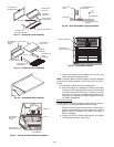
Fig. 22 — EconoMi$er Component Locations
OUTDOOR-AIR
OPENING PANEL
FILTER ACCESS
PANEL
Fig. 23 — Typical Access Panel Locations