


—
11
—
B. Field Control Wiring
Install an approved accessory thermostat assembly accord-
ing to installation instructions included with the accessory.
Locate thermostat assembly on a solid wall in the condi-
tioned space to sense average temperature in accordance
with thermostat installation instructions.
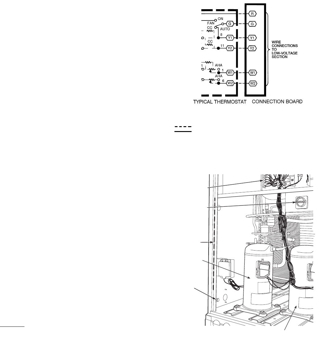
Route thermostat cable or equivalent single leads of colored
wire from subbase terminals to low-voltage connections on
unit (shown in Fig. 8) as described in Steps 1 through 4
below.
NOTE: If using Bryant electronic thermostat, set thermostat
configuration for “non-heat pump operation.” The use of the
O terminal is not required to energize the reversing valve in
this family of products.
NOTE: For wire runs up to 50 ft, use no. 18 AWG (American
Wire Gage) insulated wire (35 C minimum). For 51 to 75 ft,
use no. 16 AWG insulated wire (35 C minimum). For over
75 ft, use no. 14 AWG insulated wire (35 C minimum). All
wire larger than no. 18 AWG cannot be directly connected to
the thermostat and will require a junction box and splice at
the thermostat.
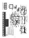
1. If unit is mounted on roof curb and accessory thru-
the-curb service plate connection is used, route wire
through connection plate.
2. Pass control wires through the hole provided on unit
(see connection D in Connection Sizes table in Fig. 6).
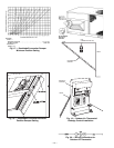
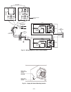
3. Feed wire through the raceway built into the corner
post to the 24-v barrier located on the left side of the
control box. See Fig. 9. The raceway provides the UL
required clearance between the high- and low-voltage
wiring.
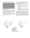
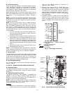
4. Connect thermostat wires to screw terminals of low-
voltage connector (see Fig. 8).
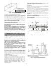
NOTE: If thru-the-bottom power connections are used refer
to the accessory installation instructions for information on
power wiring. Refer to Fig. 6 for drilling holes in basepan.
C. Defrost Board
The defrost board timer cycle is set to 30 minutes. To change
the cycle time, remove the wire from defrost board connected
to the 30-minute quick-connect. See Fig. 10. Connect the
wire to the 50 or 90 minute quick-connects on the defrost
board, depending on the desired defrost time.
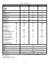
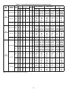
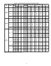
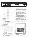
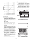
D. Heat Anticipator Settings
For units with electric heat, set heat anticipator settings as
shown in Table 3.
VI. STEP 6 — ADJUST FACTORY-INSTALLED OPTIONS
A. Disconnect Switch
The optional disconnect switch is non-fused. The switch has
the capability of being locked in place for safety purposes.
(See Fig. 9.)
B. Optional Durablade Economizer
The optional economizer hood assembly is packaged and
shipped in the filter section. Damper blades and control
boards are installed at the factory and the economizer is
shipped in the vertical discharge position.
NOTE: Horizontal discharge block-off plate is shipped with
the air hood package. If unit is to be used for vertical dis-
charge application, discard this plate.
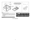
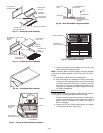
Assembly
1. Determine if ventilation air is required in building. If
so, determine the minimum amount to be supplied by
each unit and record quantity of ventilation air
needed for use in Step 8.
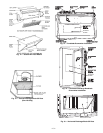
2. Remove filter access panel by raising panel and
swinging panel outward. Panel is now disengaged
from track and can be removed. No tools are required
to remove filter access panel. Remove outdoor-air
opening panel. Save panels and screws. See Fig. 11.
Remove optional outdoor-air damper hood package
from filter section.
3. Assemble outdoor-air hood top and side plates as
shown in Fig. 12. Install seal strips on hoop top and
sides. Put aside screen retainer and retainer screw
for later assembly. Do not attach hood to unit at this
time.
COMPRESSOR
NO. 2
DISCONNECT
BOARD
DISCONNECT
SWITCH
(OPTIONAL)
RACEWAY
HOLE IN
END
PANEL
COMPRESSOR NO. 1
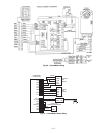
LEGEND
Fig. 8 — Low-Voltage Connections
AHA —
Adjustable Heat Anticipator
CC —
Cooling Compensator
Field Wiring
Factory Wiring
Fig. 9 — Typical Field Control Wiring Raceway