


—
32
—
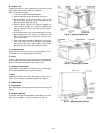
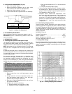
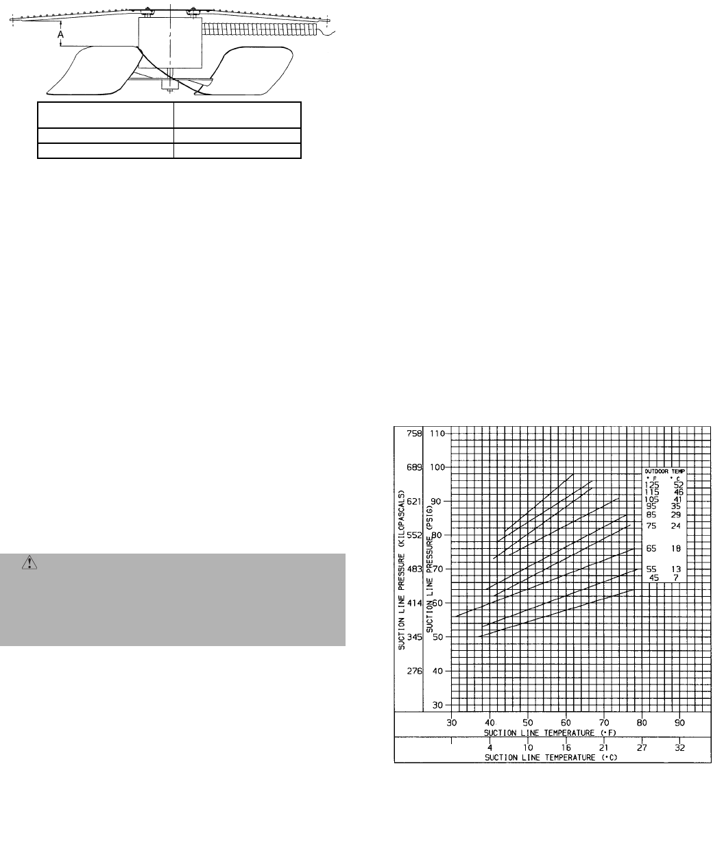
III. OUTDOOR FAN ADJUSTMENT (Fig. 42)
1. Shut off unit power supply.
2. Remove outdoor-fan assembly (grille, motor, motor
cover, and fan) and loosen fan hub setscrews.
3. Adjust fan height as shown in Fig. 42.
4. Tighten setscrews and replace outdoor-fan assembly.
IV. ECONOMIZER ADJUSTMENT
Refer to Optional Economizer sections on pages 11 and 15.
IMPORTANT: Refer to Troubleshooting Tables 14-16 for addi-
tional information.
V. REFRIGERANT CHARGE
A. Checking and Adjustment Refrigerant Charge
The refrigerant system is fully charged with R-22 refriger-
ant, tested, and factory-sealed. Unit must operate in cooling
mode a minimum of 10 minutes before checking charge.
NOTE: Adjustment of the refrigerant charge is not required
unless the unit is suspected of not having the proper R-22
charge.
A superheat charging chart is attached to the outside of the
service access panel. The chart includes the required suction
line temperature at given suction line pressures and outdoor
ambient temperatures.
An accurate superheat, thermocouple- or thermistor-type
thermometer and a gage manifold are required when using
the superheat charging method for evaluating the unit
charge. Do not use mercury or small dial-type thermometers
because they are not adequate for this type of measurement.
Proceed as follows:
1. Remove caps from low- and high-pressure service
fittings.
2. Using hoses with valve core depressors, attach low-
and high-pressure gage hoses to low- and high-
pressure service fittings, respectively.
3. Start unit in Cooling mode and let unit run until sys-
tem pressures stabilize.
4. Measure and record the following:
a. Outdoor ambient-air temperature (F db).
b. Evaporator inlet-air temperature (F wb).
c. Suction-tube temperature (F) at low-side service
fitting.
d. Suction (low-side) pressure (psig).
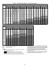
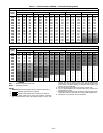
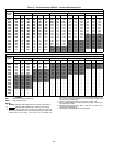
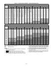
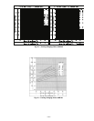
5. Using “Cooling Charging Charts” compare outdoor-
air temperature (F db) with the suction line pressure
(psig) to determine desired system operating suction
line temperature. See Fig. 43-45.
6. Compare actual suction-tube temperature with
desired suction-tube temperature. Using a tolerance
of ± 3° F, add refrigerant if actual temperature is
more than 3° F higher than proper suction-tube tem-
perature, or remove refrigerant if actual temperature
is more than 3° F lower than required suction-tube
temperature.
B. To Use Cooling Charging Charts
Take the outdoor ambient temperature and read the suction
pressure gage. Refer to appropriate chart to determine what
the suction temperature should be. If suction temperature is
high, add refrigerant. If suction temperature is low, carefully
recover some of the charge. Recheck the suction pressure as
charge is adjusted.
EXAMPLE: (Fig. 43)
Outdoor Temperature . . . . . . . . . . . . . . . . . . . . . . . . . . . . 85 F
Suction Pressure . . . . . . . . . . . . . . . . . . . . . . . . . . . . . .70 psig
Suction Temperature should be . . . . . . . . . . . . . . . . . . . . 49 F
(Suction Temperature may vary ±5° F.)
C. Heating Mode Charge
Do not attempt to adjust charge by cooling methods while in
Heating mode. When charging is necessary in Heating mode,
recover refrigerant and weigh in according to unit data plate
refrigerant data.
CAUTION: When evaluating the refrigerant
charge, an indicated adjustment to the specified fac-
tory charge must always be very minimal. If a substan-
tial adjustment is indicated, an abnormal condition
exists somewhere in the cooling system, such as insuf-
ficient airflow across either coil or both coils.
Fig. 42 — Outdoor Fan Adjustment
UNIT
VOLTAGE
‘‘A’’
in.
208/230 V
2.75
460 V and 575 V
3.50
Fig. 43 — Cooling Charging Chart, 548D090