


—
16
—
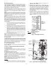
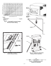
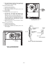
11. Install the complete hood assembly on the unit and
secure using the screws provided.
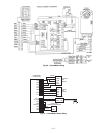
NOTE: If optional power exhaust is being installed, complete
installation of power exhaust at this time. See Fig. 32 for
wiring.
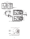
12. Remove the indoor fan motor access panel.
13. Mount the supply air temperature sensor to the lower
left portion of the indoor blower housing with the two
(2) screws provided (see Fig. 33). Connect the violet
and pink wires to the corresponding connections on
the supply air temperature sensor. Replace the indoor
fan motor access panel.
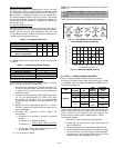
CO
2
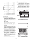
Control Set Up
If a CO
2
sensor is not being used, proceed to the next section.
If a CO
2
sensor is being used, perform the following:
1. Determine the value at which you want the minimum
position of the dampers to begin opening to allow a
greater amount of outdoor air to enter. The range is
800 to 1,400 ppm.
2. Locate the CO
2
SP (PPM) potentiometer and adjust
to the desired set point. See Fig. 34.
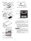
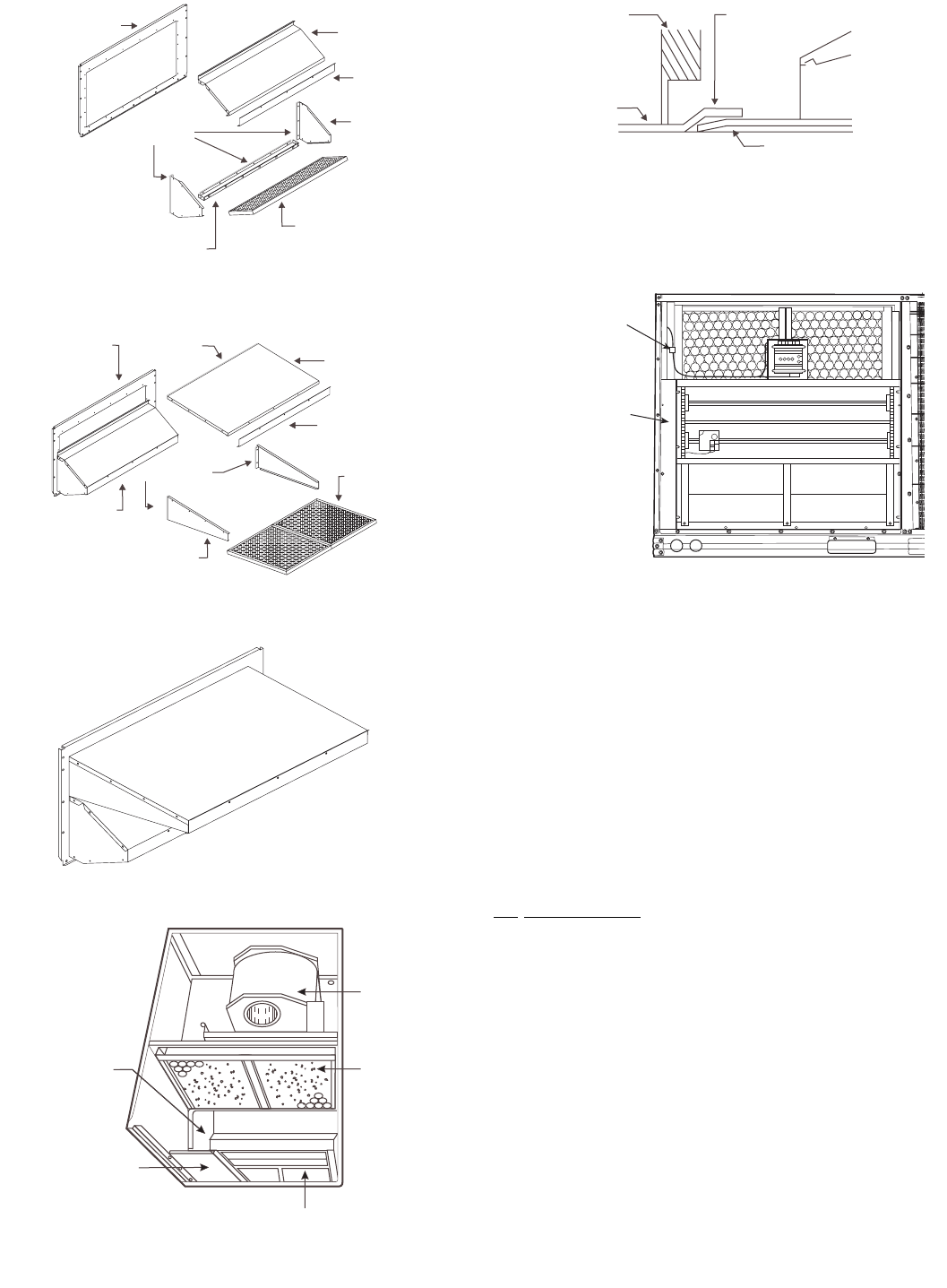
OUTDOOR AIR
OPENING PANEL
SEAL STRIP
EXHAUST AIR SCREEN
EXHAUST AIR
HOOD TOP
SCREEN
RETAINER
EXHAUST AIR
HOOD SIDES
EXHAUST AIR
BOTTOM BRACKET
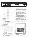
Fig. 24 — Exhaust Air Hood Assembly
SEAL STRIP
SEAL STRIP
OUTDOOR AIR
HOOD TOP
SCREEN
RETAINER
OUTDOOR AIR
INLET
SCREENS
OUTDOOR AIR
HOOD SIDES
ASSEMBLED
EXHAUST HOOD
OUTDOOR AIR
OPENING
PANEL
Fig. 25 — Outdoor Air Hood Assembly
Fig. 26 — Completed Hood Assembly
BLOWER
FILTER
RETURN AIR
BLOCK-OFF
PLATE
OUTDOOR AIR
BLOCK-OFF PLATE
ECONOMI$ER
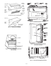
Fig. 27 — Return Air Block-Off Plate Installation
ECONOMIZER
ECONOMIZER REAR
FLANGE
UNIT BASE
UNIT FILTER
RACK
ECONOMIZER CLIP
HVAC UNIT
Fig. 28 — Rear EconoMi$er Flange Installation
WIRING HARNESS
OUTDOOR AIR
BLOCK-OFF PLATE
Fig. 29 — EconoMi$er Installed