


—
19
—
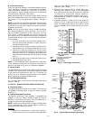
Mechanical Cooling Lockout
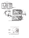
Determine the outdoor-air temperature at which you want
the mechanical cooling (compressors) to be disabled. Locate
the mechanical cooling lockout (MECH CLG LOCKOUT)
potentiometer. To disable this feature, turn the potentiome-
ter counterclockwise (CCW) to the OFF position. Otherwise,
set the value between 10 and 60 F. Mechanical cooling will
not operate when the outdoor-air temperature is below this
value. See Fig. 34.
Dry Bulb Changeover Set Up
Determine the dry bulb changeover set point from Table 4.
The settings are A, B, C and D. Locate the ECON SP potenti-
ometer and set the dry bulb changeover set point. See
Fig. 34. When the OAT is above this set point, the damper is
limited to minimum position setting.
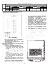
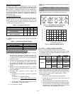
Table 4 — Changeover Set Points
*Field-installed accessory.
If a potentiometer fails, its setting will default to the values
in Table 5.
Table 5 — Default Potentiometer Settings
Ventilation Air (Minimum Position Set Up)
If ventilation air is not required, proceed to Step 5. If ventila-
tion air is required, perform the following:
1. The indoor fan must be on to set the ventilation air.
Either put the thermostat in the continuous fan mode
or jumper the R and G terminals at the rooftop unit
connection board.
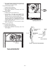
2. Locate the minimum position (MIN POS) potentiome-
ter. Turn the potentiometer full CCW to fully close
the outdoor air dampers. Turn the potentiometer
gradually clockwise (CW) to the desired position. See
Fig. 34.
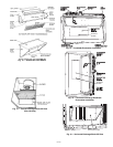
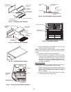
3. Replace the filter access panel. See Fig. 11. Ensure
the filter access panel slides along the tracks and is
securely engaged.
4. Calculate the minimum airflow across the
EconoMi$er.
a. Calculate % of outside air using the following
formula.
% Outdoor air through EconoMi$er
b. Divide total CFM by percentage outdoor air, this
gives outdoor air volume in CFM.
5. Turn on base unit power.
NOTE: The EconoMi$er begins operation three minutes after
power up.
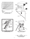
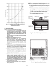
See Fig. 35 for barometric relief damper characteristics.
VII. STEP 7 — ADJUST INDOOR-FAN SPEED
Adjust indoor-fan speed to meet jobsite requirements.
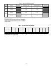
For units with electric heat, required minimum cfm is 2250
for 548D090, 2550 for 548D102 and 3000 for 548D120 with
the following exceptions:
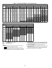
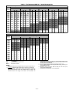
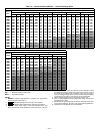
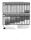
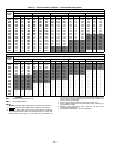
Table 6 shows indoor-fan motor data. Table 7 shows fan rpm
at motor pulley settings for standard and alternate motors.
Refer to Tables 8-13 to determine fan rpm settings. Fan
motor pulleys are factory set for speed shown in Table 1.
To change fan speeds:
1. Shut off unit power supply and tag disconnect.
2. Loosen belt by loosening fan motor mounting nuts
See Fig. 36 and 37.
3. Loosen movable pulley flange setscrew (see Fig. 38).
4. Screw movable flange toward fixed flange to increase
fan rpm or away from fixed flange to decrease speed.
Increasing fan rpm increases load on motor. Do not
exceed maximum speed specified in Table 1.
SETTINGS ABCD
Dry Bulb (°F)
73 69 66 63
Single Enthalpy* (Btu/lb)
27 25 24 22
Differential Temperature*
(°F, Not Adjustable)
2222
Differential Enthalpy*
(Btu/lb, Not Adjustable)
1111
POTENTIOMETER DEFAULT SETTING
CO
2
SP (PPM)
1,000
MECH CLG LOCKOUT
47°
ECON SP
D
MIN POS (%)
20
% Outdoor air =
Mixture Temp – Return Air Temp
Outdoor Temp – Return Air Temp
WARNING: PERSONAL INJURY HAZARD. Avoid
possible injury by keeping fingers away from damper
blades.
UNIT
UNIT
VOLTAGE
HEATER
kW
UNIT
CONFIG-
URATION
REQUIRED
MINIMUM
CFM
548D120
208/230 42.4 Horizontal 3200
208/230 50.0 Horizontal 3200
460 50.0
Horizontal
or
Vertical
3200
575
17.0 Horizontal
or
Vertical
2800
51.0 2350
Fig. 34 — EconoMi$er Control Adjustment
Potentiometers (Factory Settings)
0
200
400
600 800 1000
1200
1400 1600
FLOW (CUBIC FEET/MINUTE)
0.5
0.4
0.3
0.2
0.1
0
STATIC PRESSURE (IN. WG)
Fig. 35 — Barometric Relief Capacity