


—
3
—
II. STEP 2 — FIELD FABRICATE DUCTWORK
On vertical discharge units, secure all ducts to roof curb and
building structure. Do not connect ductwork to unit. For hori-
zontal applications, field-supplied flanges should be attached
to horizontal discharge openings and all ductwork attached
to the flanges. Insulate and weatherproof all external duct-
work, joints, and roof openings with counter flashing and
mastic in accordance with applicable codes.
Ducts passing through an unconditioned space must be insu-
lated and covered with a vapor barrier.
If a plenum return is used on a vertical unit, the return
should be ducted through the roof deck to comply with ap-
plicable fire codes.
A minimum clearance to combustibles is not required around
ductwork on vertical discharge units. On horizontal discharge
units with electric heat, a minimum clearance of 1 in. is
required for the first 12 in. of ductwork. Cabinet return-air
static should not exceed –0.35 in. wg with Durablade econo-
mizer, –0.30 in. wg with EconoMi$er, or –0.45 in. wg without
economizer.
III. STEP 3 — INSTALL CONDENSATE DRAIN LINE AND
EXTERNAL TRAP
Condensate drain connections are located on the bottom and
end of the unit. Unit discharge connections do not determine
the use of drain connections; either drain connection can be
used in vertical or horizontal applications.
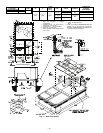
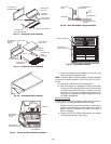
When using the standard end drain connection, make sure
the plug (Red) in the alternate bottom connection is tight
before installing the unit.
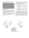
To use the bottom drain connection for a roof curb installa-
tion, relocate the factory-installed plug (Red) from the bot-
tom connection to the end connection. See Fig. 3. The piping
for the condensate drain and external trap can be completed
after the unit is in place.
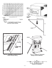
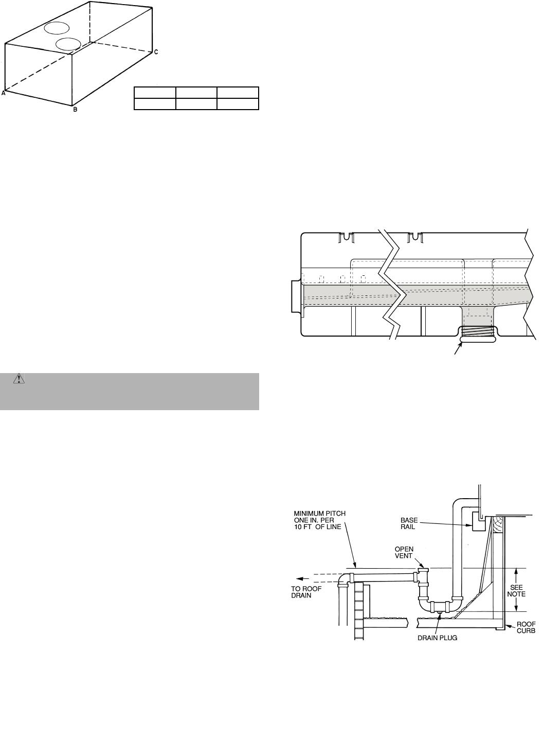
All units must have an external trap for condensate drain-
age. Install a trap at least 4-in. deep and protect against
freeze-up. See Fig. 4. If drain line is installed downstream
from the external trap, pitch the line away from the unit at
1 in. per 10 ft of run. Do not use a pipe size smaller than the
unit connection (
3
/
4
in.).
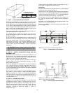
IV. STEP 4 — RIG AND PLACE UNIT
Inspect unit for transportation damage. File any claim with
transportation agency. Keep unit upright and do not drop.
Spreader bars are not required if top crating is left on unit.
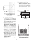
Rollers may be used to move unit across a roof. Level by
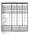
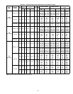
using unit frame as a reference. See Table 1 and Fig. 5 for
additional information. Operating weight is shown in
Table 1 and Fig. 5.
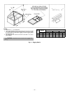
Lifting holes are provided in base rails as shown in Fig. 5
and 6. Refer to rigging instructions on unit.
Positioning
Maintain clearance around and above unit to provide proper
airflow and service access. See Fig. 6.
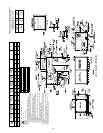
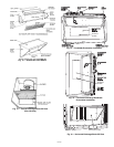
Position unit on roof curb so that the following clearances are
maintained:
1
/
4
-in. clearance between roof curb and base rails
on each side and in duct end of unit; 3
5
/
16
-in. clearance between
roof curb and condenser end (see Fig. 1, section C-C).
Do not install unit in an indoor location. Do not locate unit
air inlet near exhaust vents or other sources of contami-
nated air.
Although unit is weatherproof, guard against water from
higher level runoff and overhangs.
After unit is in position, remove polyethylene shipping wrap-
per and rigging skid.
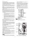
CAUTION: Ensure voltage listed on unit data
plate agrees with electrical supply provided for the
unit.
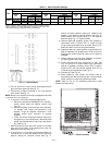
MAXIMUM ALLOWABLE
DIFFERENCE (in.)
A-B B-C A-C
0.5 1.0 1.0
Fig. 2 — Unit Leveling Tolerances
DRAIN PLUG
NOTE:
Drain plug is shown in factory-installed position.
Fig. 3 — Condensate Drain Connection
NOTE:
Trap should be deep enough to offset maximum unit static dif-
ference. A 4-in. trap is recommended.
Fig. 4 — External Trap Condensate Drain