


Copyright 2000 Bryant Heating & Cooling Systems CATALOG NO. 5354-805
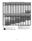
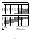
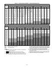
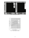
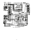
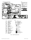
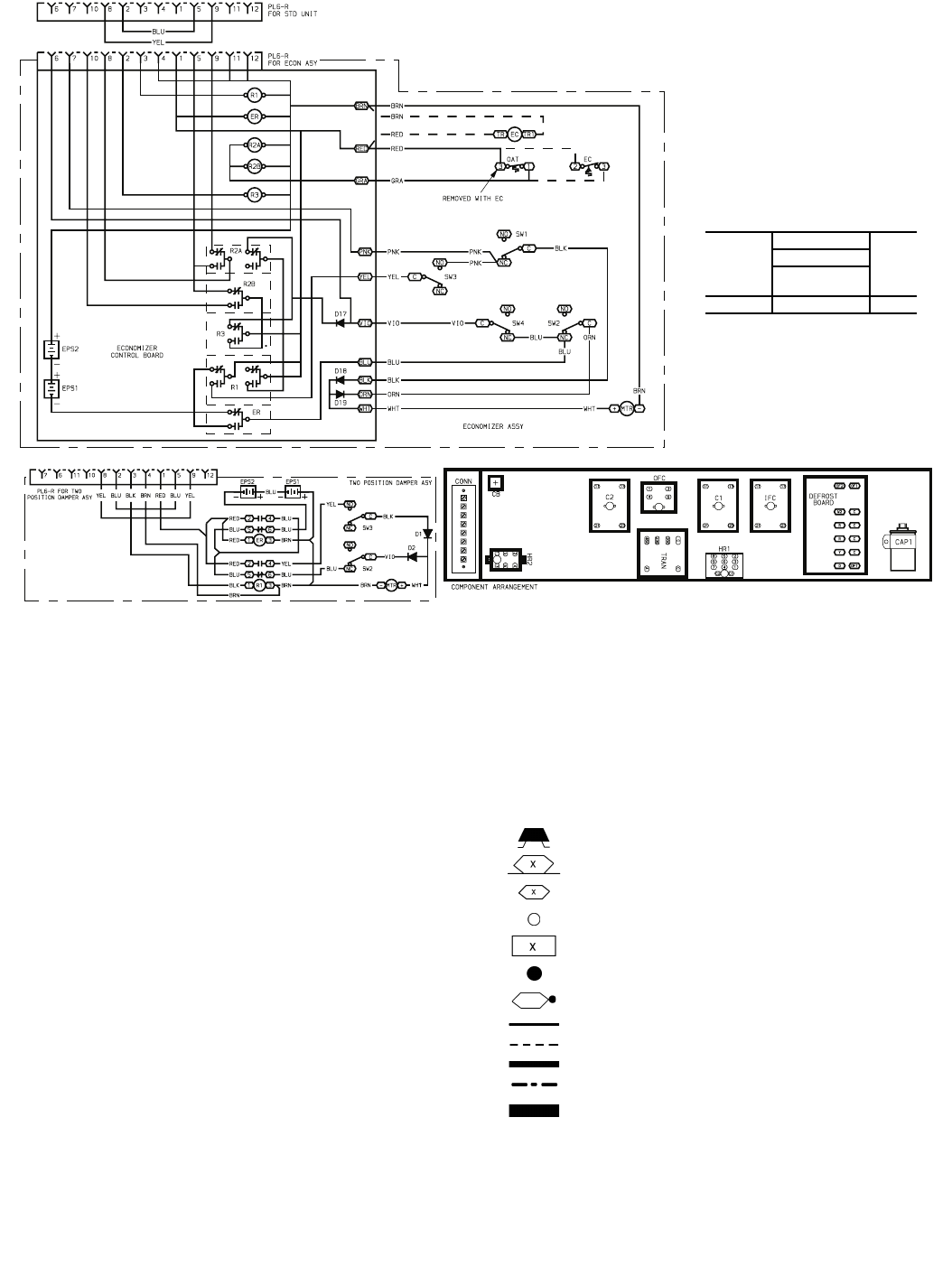
Fig. 46 — Typical Wiring Diagram (cont)
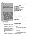
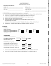
NOTES:
1. If any of the original wire furnished
must be replaced, it must be
replaced with type 90° C wire or its
equivalent.
2. Three-phase motors are protected
under primary single-phasing
conditions.
3. Thermostat: HH07AT172 and
P272-2783
Subbase: HH93AZ176, 178 and
P272-1882, 1883
4. Set Heat anticipator at .8 amp for
1st stage and .3 amp for 2nd stage.
5. Use copper conductors only.
6. Use copper, copper clad aluminum
or aluminum conductors.
7.
VOLTAGE
RATING
CB
MUST
TRIP
AMPS
Mfg. Pt. No.
Potter &
Brumfield
24 V W28X-1024-3.2 3.2
AHA —
Adjustable Heat Anticipator
AWG —
American Wire Gage
C —
Contactor, Compressor
CAP —
Capacitor
CB —
Circuit Breaker
CC —
Cooling Capacitor
CH —
Crankcase Heater
CLO —
Compressor Lockout
COMP —
Compressor Motor
D —
Diode
DB —
Defrost Board
DFT —
Defrost Thermostat
EC —
Enthalpy Control
ECON —
Economizer
EPS —
Emergency Power Supply
(nine volt battery)
EQUIP —
Equipment
ER —
Economizer Relay
FPT —
Freeze-Up Protection Thermostat
FU —
Fuse
GND —
Ground
HC —
Heater Contactor (Strip Heat)
HPS —
High-Pressure Switch
HR —
Heater Relay
IFC —
Indoor Fan Contactor
IFM —
Indoor Fan Motor
IFMOVL —
Indoor Fan Motor Overload Switch
LPS —
Low-Pressure Switch
LSM —
Limit Switch (Manual Reset)
MCA —
Minimum Circuit Amps
MTR —
Motor
OAT —
Outdoor Air Thermostat
OFC —
Outdoor Fan Contactor
OFM —
Outdoor Fan Motor
P —
Plug
PL —
Plug Assembly
QT —
Quadruple Terminal
R —
Relay
RVS —
Reversing Valve Solenoid
SAT —
Supply Air Thermostat
SW1 —
Switch Fully Open
SW2 —
Switch Fully Closed
SW3 —
Switch Minimum Vent Position
SW4 —
Switch Maximum Vent Position
TB —
Ter minal Block
TC —
Thermostat-Cooling
TH —
Thermostat-Heating
TRAN —
Transformer
Field Splice
Marked Wire
Terminal (Marked)
Terminal (Unmarked)
Ter minal Block
Splice
Spliced (Marked)
Factory Wiring
Field Control Wiring
Field Power Wiring
Accessory or Optional Wiring
To indicate common potential only,
not to represent wiring.
LEGEND