


—9—
IV. COMPLETE ELECTRICAL CONNECTIONS
A. Power Supply
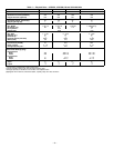
Electrical characteristics of available power supply must
agree with nameplate rating. Supply voltage must be within
tolerances shown in Table 7. Phase imbalance must not
exceed 2%. Operation of unit on improper supply voltage or
with excessive phase imbalance constitutes abuse and is not
covered by Bryant warranty.
Per local code requirements, provide an adequate fused
disconnect switch within sight of unit and out of reach of
children. Provision the switch for locking open (off) to
prevent power from being turned on while unit is being
serviced. The disconnect switch, fuses, and field wiring must
comply with local requirements. Refer to Table 7 for unit
electrical data.
B. Power Wiring
All power wiring must comply with applicable local require-
ments. Run power wires from disconnect switch through unit
power opening and connect to terminal block inside the unit
control box. Unit must be grounded.
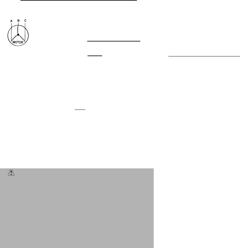
C. Unbalanced 3-Phase Supply Voltage
Never operate a motor where a phase imbalance in supply
voltage is greater than 2%. Use the following formula to
determine the percentage of voltage imbalance:
% Voltage Imbalance:
Example: Supply voltage is 460-3-60.
AB = 452 v
BC = 464 v
AC = 455 v
= 457
(AB) 457 – 452 = 5 v
(BC) 464 – 457 = 7 v
(AC) 457 – 455 = 2 v
Maximum deviation is 7 v.
Determine percent of voltage imbalance.
% Voltage Imbalance= 100 x
= 1.53%
This amount of phase imbalance is satisfactory as it is below
the maximum allowable 2%.
IMPORTANT: If the supply voltage phase imbalance is
more than 2%, contact your local electric utility company
immediately.
IMPORTANT: Operation of unit on improper power supply
voltage or with excessive phase imbalance constitutes abuse
and is not covered by Bryant warranty.
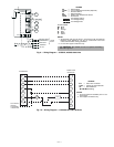
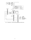
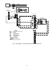
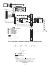
D. General Wiring Notes (See Fig. 8-13)
1. A crankcase heater is wired in the control circuit so it
is always operable as long as power supply disconnect
is on, even if any safety device is open or unit stop/
start switch is off.
2. The power-circuit field supply disconnect should
never be open except when unit is being serviced or is
to be down for a prolonged period. When operation is
resumed, crankcase heater should be energized for
24 hours before start-up. If system is to be shut down
for a prolonged period, it is recommended that the
suction and discharge valves be closed to prevent
an excessive accumulation of refrigerant in the com-
pressor oil.
3. Terminals for field power supply are suitable for cop-
per, copper-clad aluminum, or aluminum conductors.
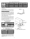
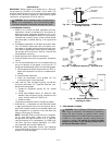
4. Bryant recommends an indoor airflow switch (field
supplied) be installed and interlocked with the
outdoor unit. This prevents the outdoor unit from
operating if indoor airflow fails (broken fan belt, etc.).
Operation of the compressor in vacuum can damage
bearing surfaces. Install indoor airflow switch in a
convenient location at the indoor supply air duct and
wire per Fig. 14.
5. If the system is equipped with an accessory electric
heater, refer to the 524A-H installation instructions
and tables.
E. Control Circuit Wiring
Control voltage is 24 v. See unit label diagram for field
supplied wiring details. Route control wires through opening
in unit to connection in unit control box.
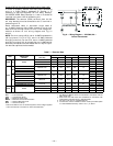
Control Transformer Wiring
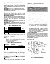
On 208/230V units, check the transformer primary wiring
connections. See Fig. 8 or refer to unit label diagram.
For 575B,C Unit — If unit will be operating at 208-3-60
power, remove black wire (BLK) from the transformer pri-
mary connection labeled “230” and move it to the connection
labeled “208”. See Fig. 8.
For 541A Unit — Transformers no. 1 and 2 are wired for a
230-v unit. If a 208/230-v unit is to be run with a 208-v
power supply, the transformers must be rewired as follows:
1. Remove cap from red (208 v) wire.
2. Remove cap from orange (230 v) spliced wire.
3. Replace orange wire with red wire.
4. Recap both wires.
IMPORTANT: BE CERTAIN UNUSED WIRES ARE
CAPPED. Failure to do so may result in damage to the
transformer.
= 100 x
max voltage deviation from average voltage
average voltage
Average Voltage =
452 + 464 + 455
3
=
1371
3
WARNING: Unit cabinet must have an uninter-
rupted, unbroken electrical ground to minimize the
possibility of personal injury if an electrical fault
should occur. This ground may consist of electrical wire
connected to unit ground lug in control compartment,
or conduit approved for electrical ground when
installed in accordance with NEC (National Electrical
Code), ANSI/NFPA (American National Standards
Institute/National Fire Protection Association), and
local electrical codes. Failure to follow this warning
could result in the installer being liable for personal
injury of others.
7
457