


—15—
PRE-START-UP
IMPORTANT: Before beginning Pre-Start-Up or Start-Up,
review Start-Up Checklist at the back of this book. The
checklist assures proper start-up of the system and provides
a record of unit condition, application requirements, system
information, and operation at initial start-up.
I. PRELIMINARY CHECKS
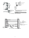
1. Check all air handler and other equipment auxiliary
components. Consult manufacturer’s instructions re-
garding any other equipment attached to unit. If unit
has field-installed accessories, be sure all are properly
installed and correctly wired. If used, airflow switch
must be properly installed. See Fig. 14 for typical field
wiring.
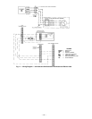
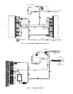
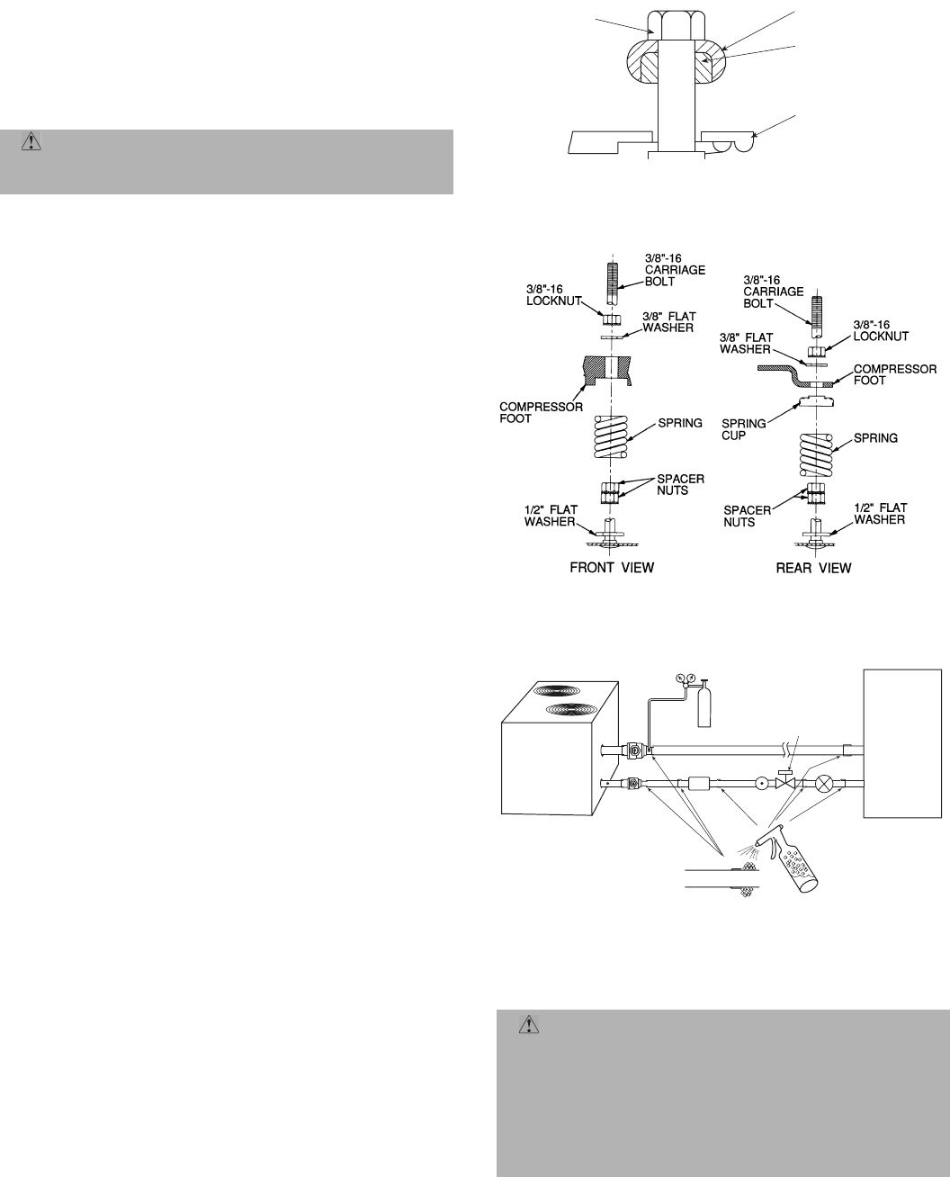
2. As shipped, compressor is held down by 4 bolts. After
unit is installed, loosen each bolt and locknut until
flat washer or snubber can be moved with finger pres-
sure. Be sure compressor floats freely on the mount-
ing springs (541A units only). See Fig. 15A and 15B
for compressor mounting.
3. Check tightness of all electrical connections.
4. Electrical power source must agree with nameplate
rating.
5. Turn on crankcase heater for 24 hours before starting
the unit to be sure all refrigerant is out of the oil. To
energize crankcase heater, perform the following steps:
a. Set the space thermostat system switch to OFF, or
adjust the temperature so there is no demand for
cooling.
b. Close the field disconnect.
c. Leave the compressor circuit breaker off. The
crankcase heater is now energized.
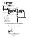
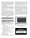
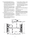
6. Leak test the field refrigerant piping, connections
and joints, and indoor coil. To perform leak test, com-
plete the following steps:
a. Pressurize refrigerant piping; do not exceed
150 psi.
b. Using soap bubbles and/or an electronic leak
detector, test refrigerant piping, connections and
joints, and the indoor coil. See Fig. 16.
c. Check for leaks.
Evacuate and dehydrate entire refrigerant system.
7. 541A180 only — compressor oil level should be visible
in sight glass. Adjust the oil level as required. No oil
should be removed unless the crankcase heater has
been energized for at least 24 hours. See Start-Up
section, Preliminary Oil Charge.
NOTE: The 575B, 575C units do not have a compres-
sor oil level sight glass. These units are factory
charged with the required amount of oil. If required,
use the following oil for replacement: For 575B units
use Zerol 150, part number P903-2001. For 575C
units use RCD, part number P903-0101.
8. Backseat (open) compressor suction and discharge
valves. Now close valves one turn to allow refrigerant
pressure to reach test gages.
II. PRELIMINARY CHARGE
CAUTION: Do not attempt to start the heat pump
system, even momentarily, until the following steps
have been completed. Compressor damage may result.
CAUTION: The 575C090 and 575C120 units contain a
9 lb charge of refrigerant. Add remainder of preliminary
charge and allow pressure to equalize before starting
compressor. Failure to do so WILL cause the compressor to
overheat in a few minutes, possibly causing permanent
compressor damage. The amount of refrigerant added
must be at least 80% of the operating charge listed in
the Physical Data table (Table 1).
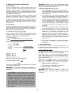
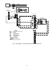
OUTDOOR
UNIT
INDOOR
COIL
SOAP
TXV
SUCTION LINE
LIQUID LINE
DRY
NITROGEN
150 PSI MAX
LIQUID LINE
SOLENOID VALVE
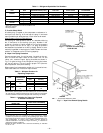
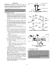
Fig. 15B — Compressor Mounting — 541A180 Units
SELF-LOCKING
BOLT
SNUBBER WASHER
NEOPRENE
SNUBBER
COMPRESSOR FOOT
Fig. 15A — Compressor Mounting — 575B072 and
575C090,120 Units
→ Fig. 16 — Recommended Process for
Checking for Leaks